- Blog
An ESD tray with dividers can make an SMT kit visible at the point of use, but only when every cell, handoff, and replenishment decision has an owner. Treat the tray as one physical element of the kit process—not as proof that the kit is complete or that a particular configuration is approved.
For broader tray selection, start with this ESD tray staging guide. This article focuses on the daily operating question: how a shallow divided tray can present the next defined kit beside an SMT station without becoming an unowned collection point.
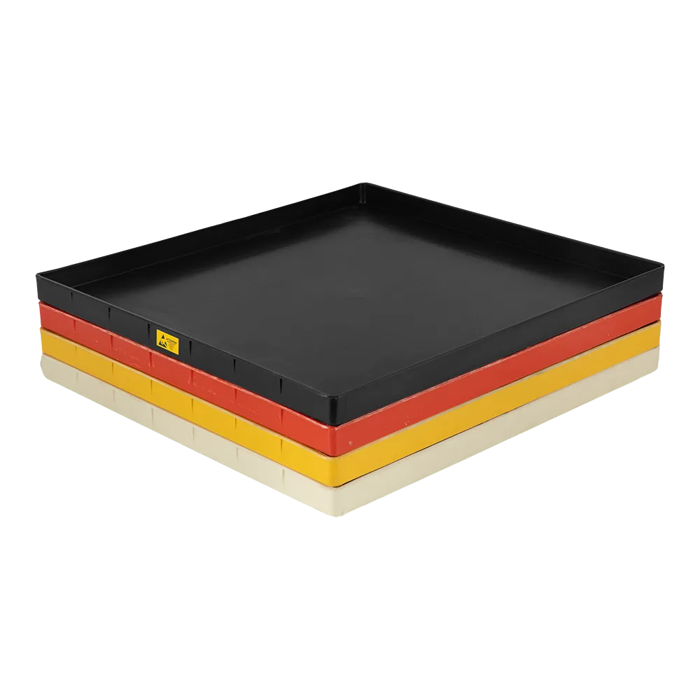
Part 1. What role should the tray play at the line?
Start with the operating job, not the number of dividers. A line-side tray is useful when an operator needs shallow, visible access to a defined component kit at a known workstation.
That role differs from an ESD box with dividers. A box can be selected for an enclosed storage or movement task; a tray here is selected for point-of-use presentation, clear cell allocation, and a controlled return for replenishment.
| If the process needs… | Define the tray as… | Do not assume… |
|---|---|---|
| The next job’s staged components | A named kit at a named station | The tray confirms every required item is present |
| Fast visual selection | A shallow presentation surface with assigned cells | A cell is interchangeable with another cell |
| A handoff to materials | A returnable kit record with a receiving owner | An empty tray automatically signals a shortage |
| Protection during extended storage or a transport route | A separate packaging or enclosure decision | A line-side tray is that enclosure |
When the line is buffering PCBs between machines, use the process-specific PCB tray overview or a magazine-rack review instead of assigning that job to a loose-parts kit tray.
Part 2. Who owns the kit and each cell?
Before loading begins, name one owner for the kit state. The owner may be the materials team, a kitting station, or an identified production role; the important point is that the work instruction identifies who releases, receives, and resolves an exception.
Cell allocation should connect a physical location to a defined item, lot rule, and status. A label can support that connection, but the buyer’s own material-control method remains the system of record.
| Control point | Record before release | Why it matters |
|---|---|---|
| Kit ownership | Responsible role and handoff point | Prevents an unattended tray from becoming shared inventory |
| Work-order boundary | Order, build, or approved kit identifier | Keeps one job from blending into the next |
| Cell allocation | Item reference, permitted quantity or pack, and location | Makes a missing or wrong item visible |
| Lot rule | Whether a cell may contain more than one lot | Avoids unapproved mixing |
| Status | Released, hold, return, or replenish state | Gives operators a clear escalation cue |
Do not rely on tray color or position alone. If two kits can look similar, the visible identifier and cell allocation need to distinguish them.
Part 3. What belongs in a divider plan?

Use the part envelope rather than a nominal component name to make the divider plan. Include packaging, reels, protective bags, labels, connectors, and the motion needed to pick or return the item.
The plan does not need to invent a tray size. It needs to show what the supplier must evaluate: the cells, divider direction, access need, and any contact restriction.
| Divider-plan input | What the buyer supplies | Check in the sample review |
|---|---|---|
| Part envelope | Maximum occupied length, width, and height | Item can enter and leave without snagging |
| Cell allocation | One assigned item, pack, or approved group | The label agrees with the loaded content |
| Divider direction | The separation needed between adjacent items | Handling does not cause crossover |
| Pick access | Hand, tool, or automation access motion | Operators can retrieve the item consistently |
| Contact restriction | Leads, pins, surfaces, or packaging that must not touch | Adjacent cells do not create an avoidable contact risk |
Sanwei lists ESD Tray and ESD Tray With Grids product families. Ask for a quotation that identifies the selected model and whether the requested divider plan, partition, or label option is available for it; do not infer that an option applies to every tray.
Part 4. How should replenishment and shortages work?
A replenishment trigger should be observable and actionable. It can be a defined empty-cell condition, a minimum pack rule, a scan event, or a supervised visual check, provided the line and materials team use the same rule.
The shortage response belongs beside the tray, not in a memory-based workaround. State whether the operator stops, calls materials, substitutes only with written approval, or moves the kit to a hold location.
| Event | Tray rule | Owner action |
|---|---|---|
| Cell reaches its trigger point | Mark or scan the replenishment trigger | Materials receives a defined request |
| Wrong item is found | Preserve the cell identity and kit status | Quarantine or correct under the work instruction |
| Kit changes to another work order | Empty, verify, and release under the new kit record | Kitting owner confirms the handoff |
| Tray returns from the line | Check the cell allocation and visible condition | Materials decides whether to replenish, clean, or hold |
Avoid placing two active work orders into one tray unless the work instruction explicitly permits the boundary and labels. Physical dividers organize items; they do not decide authorization.
Part 5. What makes point-of-use presentation usable?
Point-of-use presentation succeeds when the tray location makes selection easy without obscuring the kit identity. Confirm the bench, cart, shelf, or feeder-side position before a tray configuration is released.
Review how the operator approaches each cell. A layout that looks orderly on a desk may become difficult when gloves, tools, lighting, or a neighboring fixture change the actual pick path.
| Presentation review | Question to answer |
|---|---|
| Sight line | Can the operator see the kit ID and cell identifiers at the normal working position? |
| Pick path | Can each item be taken and returned without crossing a neighboring cell? |
| Position | Does the selected location avoid blocking the approved workstation flow? |
| Housekeeping | Is there a defined place for an empty pack, reject, or return item? |
| Changeover | Who clears and verifies the tray before the next kit occupies it? |
For custom cavities or a dedicated interface, see custom-cavity tray guidance. That is a different evaluation from using dividers to manage a visible line-side kit.
Part 6. Which ESD and configuration details need confirmation?
An ESD program sets the acceptance context; a product image or general tray family does not. Request the buyer-required ESD evidence, test method, applicable test locations, and traceability to the selected tray or sample.
ANSI/ESD S20.20-2021 describes requirements for an ESD control program. It does not certify a particular tray, divider plan, station layout, or kit procedure.
Sanwei’s ESD Tray product family lists selected anti-static partition and label options on published model rows. Confirm the selected configuration, its available evidence, and any cleaning or handling constraints in the quotation rather than assigning material, electrical, load, or temperature claims to an unspecified tray.
Part 7. What should the RFQ and sample review include?
The RFQ should let a supplier review the kit task without guessing. Send one controlled version of the drawing or cell list, plus the intended line-side use and the buyer’s acceptance criteria.
| RFQ input | Buyer should provide |
|---|---|
| Kit definition | Work-order boundary, kit owner, and station |
| Item data | Part envelope, packaging condition, and contact restrictions |
| Cell plan | Cell allocation, divider direction, labels, and lot rule |
| Operating rule | Replenishment trigger, shortage escalation, and return path |
| Station context | Point-of-use location, access motion, and relevant interface |
| ESD request | Required method, evidence, and acceptance criteria |
| Sample-use review | Loaded handling, pick access, cell identity, divider behavior, and visual condition |
For a model-review starting point, use the Sanwei ESD Tray product family. The family can support the conversation about a quoted tray and selected options; it is not a blanket recommendation for an unmeasured kit.

Fit Boundary
| Buyer situation | Reasonable path | Avoid |
|---|---|---|
| Defined SMT kit at one point of use | Divider tray with owned cells and a replenishment rule | Treating an unlabeled tray as a complete kit |
| Need for an enclosed storage or transport arrangement | Review an ESD box or protective-packaging path | Calling a shallow tray a universal enclosure |
| PCB flow between process machines | Review a PCB carrier or magazine rack | Using a loose-parts kit tray as the inter-machine buffer |
| Unclear item dimensions or divider behavior | Supply envelopes and run a sample-use review | Choosing from a photo or divider count alone |
Send the controlled kit list, part envelopes, divider plan, station context, and ESD evidence request through Contact Sanwei for a quote-confirmed configuration review.
FAQ
What is an ESD tray with dividers used for in SMT?
It can present a defined component kit in visible, separated cells at the line. The process still needs an owner, item allocation, labeling rule, and replenishment method.
How is a divider tray different from an ESD box with dividers?
This tray workflow is for shallow point-of-use presentation and kit handling. An ESD box may be evaluated for a different enclosure, storage, or movement task, so its divider article should not be used as a tray specification.
Who should own a line-side kit tray?
Assign a named operational role or handoff point that releases the kit, receives returns, and resolves shortages. The exact role depends on the buyer’s work instruction.
What should each tray cell identify?
Record the assigned item or approved group, its lot rule, status, and the relevant kit or work-order boundary. Include the cell identifier on the controlled kit record.
Can one tray hold more than one work order?
Only if the buyer’s process explicitly allows the boundary and labels to remain unambiguous. Separate active work orders by a documented allocation and handoff rule rather than by visual guesswork.
How should a kit be replenished?
Use a defined replenishment trigger and an owner action, such as a scan, a minimum-pack condition, or a supervised visual signal. The tray should make that condition visible, not replace the materials-control process.
What ESD information should be requested for the tray and dividers?
Request the buyer-required test method, evidence, test locations where relevant, and traceability to the selected configuration or sample. Confirm those requirements in the quotation.
What should be tested on a divider-tray sample?
Check the loaded part envelope, pick and return motion, cell allocation, divider behavior, label visibility, point-of-use access, and the ESD evidence required by the buyer’s program.
Laisser un commentaire