- Turbo
- Blog
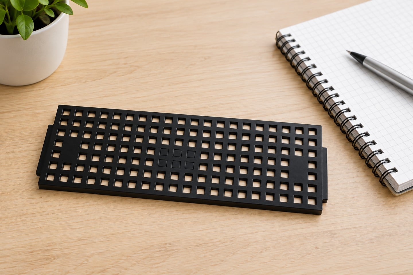
Les inserts de plateaux pour circuits intégrés (IC Tray Inserts) doivent être sélectionnés dans le cadre d'un processus défini de manipulation des composants électroniques, et non comme un article de catalogue générique. La bonne spécification relie la géométrie du composant, la fonction ESD, la protection mécanique, l'accès pour l'opérateur, les interfaces des équipements, le nettoyage et la vérification. Ce guide montre aux ingénieurs et aux acheteurs comment traduire ces besoins en une demande de devis (RFQ), un plan d'approbation des échantillons et un contrôle de réception reproductible. Il explique également où le plateau pour circuits intégrés s'intègre dans le système global de contrôle des ESD, sans supposer que la couleur, le nom d'un matériau ou un seul résultat de test prouve l'adéquation pour chaque dispositif et chaque trajet.
Ce que le produit doit faire dans le flux de travail réel
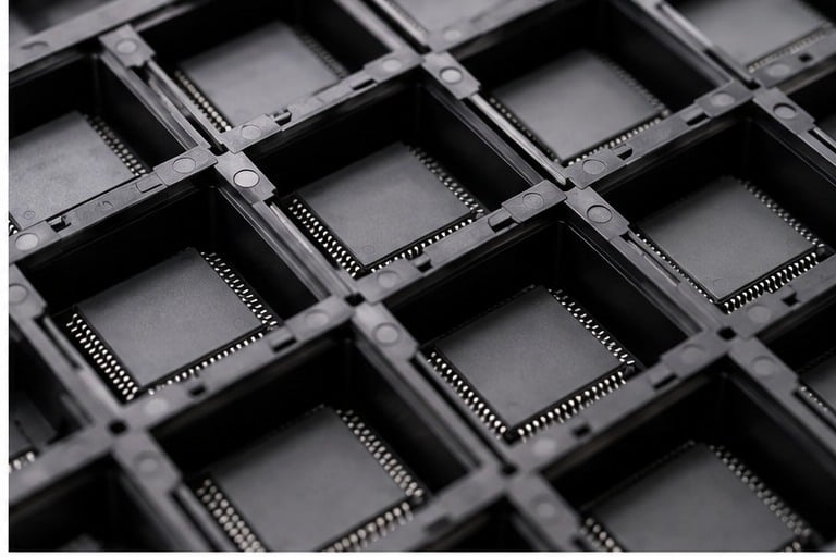
L'objectif pratique est d'adapter un plateau extérieur réutilisable à des composants plus petits, à des kits mixtes ou à une séparation spécifique à un projet tout en préservant la manipulation conforme aux ESD. Cette phrase constitue l'exigence de départ. Une spécification utile nomme l'article protégé, l'endroit où il entre dans le processus, chaque transfert, l'équipement qu'il touche, le temps pendant lequel il reste dans l'emballage et ce qui peut mal tourner. Sans cette cartographie, un plateau, une lingette, un testeur ou un chariot peut réussir un examen sur papier et échouer tout de même sur la ligne de production.
Séparez le problème de protection en trois couches. Premièrement, prévenez le contact mécanique, les mouvements incontrôlés et les mélanges. Deuxièmement, définissez la fonction électrostatique requise et sa connexion au programme de contrôle de l'installation. Troisièmement, rendez la solution utilisable : les opérateurs doivent charger, identifier, inspecter et décharger les pièces sans créer de nouveau risque. Les acheteurs doivent donc impliquer l'ingénierie des procédés, la qualité et le coordinateur ESD avant de figer la description d'achat.
Élaborer un cahier des charges avant de demander un prix
Un fournisseur ne peut chiffrer avec précision que lorsque l'appel d'offres distingue les critères d'acceptation obligatoires des préférences. Joignez des plans contrôlés plutôt que des captures d'écran, identifiez les révisions et indiquez si les dimensions sont des caractéristiques de référence ou d'inspection. Décrivez l'environnement réel, y compris les agents de nettoyage, l'exposition à la température, la plage d'humidité, la durée de stockage et toute interface automatisée. Lorsqu'une limite n'est pas encore connue, demandez un essai sur échantillon au lieu d'inventer un chiffre.
| Zone de décision | Que définir | Comment vérifier |
|---|---|---|
| En forme | Corps, broche, connecteur et zone d'exclusion | Réviser le dessin plus les échantillons |
| Rétention | Comportement de levage, d'inclinaison et de vibration | Utiliser un test spécifique à l'itinéraire |
| Accès | Prise au doigt, à la pince, par le vide ou par robot | Vérifier la méthode réelle |
| Insérer l'interface | Localisation, enlèvement, nettoyage et remplacement | Essai dans le bac extérieur |
Le tableau est délibérément axé sur la méthode. Les limites d'acceptation numériques doivent provenir du dessin de produit applicable, des données du dispositif, du plan de contrôle ESD et de la méthode d'essai référencée. Un chiffre copié sur la fiche d'un fournisseur sans rapport peut utiliser un conditionnement, une géométrie ou une tension différent et créer une fausse confiance.
Commencez par l'élément protégé, pas par le contenant
Enregistrez l'état de matière maximale de l'élément protégé, les caractéristiques fragiles, les zones de contact autorisées, l'orientation et les besoins d'identification. Pour les assemblages électroniques, les connecteurs, les joints de soudure, les conducteurs exposés et les composants hauts peuvent nécessiter des zones d'exclusion qui ne sont pas évidentes à partir de la longueur et de la largeur extérieures. Si plusieurs références partagent une seule solution, testez les configurations la plus petite, la plus grande et la plus vulnérable plutôt qu'une moyenne pratique.
Les échantillons physiques sont précieux, mais ils ne remplacent pas des données contrôlées. Un échantillon représente un résultat de production et peut ne pas révéler l'ensemble des tolérances. Utilisez les plans pour définir l'enveloppe, les échantillons pour comprendre la manipulation, et un essai de parcours pour prouver le fonctionnement. Lorsque l'article change de révision, effectuez une revue de compatibilité documentée avant de continuer à utiliser l'ancien emballage ou l'instruction de travail.
Définir la fonction ESD et la limite de test
Des termes tels que antistatique, dissipateur de charges électrostatiques et conducteur décrivent des notions différentes et sont parfois utilisés de manière imprécise. La demande de prix (RFQ) doit identifier les surfaces de contact, la fonction de contrôle de charge prévue, la méthode applicable, le conditionnement, la tension ou le montage d'essai, la plage d'acceptation et le plan d'échantillonnage. L'exigence correcte dépend de la sensibilité du dispositif, de la proximite, de la mise à la terre et de la nécessité ou non d'un blindage en plus d'une dissipation contrôlée.
Testez le système assemblé lorsque les interfaces comptent. Un échantillon de matériau ne peut pas révéler un mauvais contact entre un insert et un plateau extérieur, une étagère isolée, une roulette contaminée ou un revêtement usé à un point de manipulation. Les conditions environnementales et la propreté des surfaces doivent être consignées car elles peuvent influencer les mesures. Les résultats ne sont comparables que lorsque la méthode et les conditions le sont.
Vérifier l'ajustement mécanique, l'accès et la compatibilité des procédés
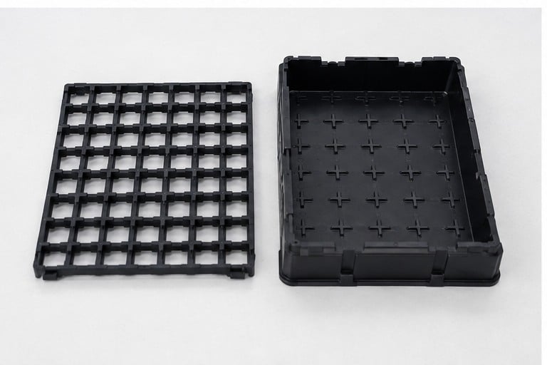
Un contrôle d'ajustement doit reproduire le chargement, le transport normal, l'empilage ou le stationnement, et le déchargement. Rechercher le basculement, le pincement, le contact avec les fils, la déflexion des cartes, la libération accidentelle et l'interférence avec les gants, les brucelles, la préhension par le vide ou l'inspection. Si la solution pénètre dans l'équipement, tester l'indexation, les capteurs, les rails et les dégagements en utilisant l'empilage et l'orientation prévus. Une simple démonstration manuelle ne constitue pas une qualification d'équipement.
La compatibilité des procédés englobe plus que les dimensions. La chimie de nettoyage peut attaquer un polymère ou laisser des résidus. L'exposition à la chaleur peut altérer la planéité. Des manipulations répétées peuvent user les éléments de positionnement. Les étiquettes peuvent s'effriter, masquer l'inspection ou laisser de l'adhésif. Documentez ces interfaces afin que le fournisseur puisse recommander un matériau et une conception pour examen, puis validez cette recommandation dans le processus réel.
Séquence de prototypage et d'approbation
- Examen sur dossier : confirmer les dessins, les révisions, l'élément protégé, l'itinéraire, la fonction ESD et le plan de réception.
- Premier article : Inspectez l'identité, la qualité d'exécution et les dimensions critiques avant d'introduire des dispositifs de valeur.
- Essai d'ajustement : charger les articles représentatifs et vérifier le contact autorisé, le dégagement, l'orientation et le retrait.
- Essai routier : reproduire l'empilement, la manutention, le transport, l'interface des équipements, le nettoyage et le stockage.
- Examen des données probantes : examiner les déclarations de matériaux et les rapports d'essai pour vérifier la méthode, le conditionnement, l'identité des échantillons et la traçabilité.
- Sortie : enregistrer l'échantillon approuvé, le plan, les déviations, les photos et les contrôles de réception.
Cette séquence verrouillée empêche un prototype attrayant de devenir un standard de production non contrôlé. Tout écart doit identifier qui l'a accepté, pour quelle pièce et quelle durée, et comment l'inventaire concerné sera contrôlé. Lorsque le fournisseur ou le matériau change, répétez les contrôles affectés par ce changement.
Contrôle à la réception et vérification continue
L'inspection à réception doit être proportionnelle au risque et à l'historique du fournisseur. Confirmez d'abord l'identité et la révision de l'achat, puis vérifiez les dommages visibles, la contamination, la distorsion, l'assemblage, les étiquettes et les interfaces critiques. Utilisez le plan d'échantillonnage convenu pour les dimensions et les contrôles électriques. Mettez les lots suspects en quarantaine avant de les mélanger au stock accepté et conservez suffisamment d'informations pour remonter du résultat jusqu'au lot du fournisseur et à l'équipement de test.
Les contrôles continus doivent porter sur les caractéristiques susceptibles de se dégrader avec l'usage : la propreté, l'usure, le gauchissement, les séparateurs endommagés, la quincaillerie desserrée, l'état des électrodes ou les chemins de mise à la terre altérés. Définissez les critères de nettoyage et de mise au rebut en termes observables. “ Utiliser jusqu'à détérioration ” n'est pas un critère ; citons pour exemples une poche fendue, un empilement instable, une identité illisible, un résidu qui ne peut pas être éliminé par le processus approuvé, ou une vérification échouée.

Erreurs courantes dans les spécifications
- Rendre les poches assez serrées pour toucher les conducteurs vulnérables. Prévenez cela en rattachant la décision à un dessin, une méthode d'essai ou un essai sur piste et en conservant les preuves d'approbation.
- Ajout de séparateurs qui bloquent la prise sous vide ou l'inspection. Prévenez cela en rattachant la décision à un dessin, une méthode d'essai ou un essai sur piste et en conservant les preuves d'approbation.
- Spécifier un insert sans définir comment il se positionne et reste maintenu à l'intérieur du plateau extérieur. Prévenez cela en rattachant la décision à un dessin, une méthode d'essai ou un essai sur piste et en conservant les preuves d'approbation.
Une autre erreur fréquente est de permettre à un label marketing de remplacer le plan de réception. Un nom de produit peut faciliter la recherche et la communication, mais les décisions relatives à la qualité exigent des preuves contrôlées. L'acheteur et le fournisseur doivent convenir de ce qui sera inspecté, de l'endroit où la mesure est effectuée, de la révision qui s'applique et de ce qui se passe lorsqu'un résultat est non conforme.
Liste de contrôle de demande de prix
- Numéros d'articles protégés, dessins, révisions, échantillons et zones de contact autorisées.
- Quantité par conteneur ou par couche, orientation et méthode de traçabilité.
- Itinéraire complet du processus, opérateurs, interfaces des équipements, conditions d'empilement et de transport.
- fonction ESD, méthode référencée, conditionnement, limites d'acceptation et enregistrements d'essais.
- Restrictions de matériaux, propreté, chimie de nettoyage et expositions environnementales.
- Dimensions critiques, tolérances et plan d'échantillonnage de premier article.
- Quantité de prototypes, séquence d'approbation et responsabilité des modifications.
- Demande de production, emballage, pièces de rechange, cycle de vie et attentes en matière de livraison.
Pour une discussion avec un fournisseur, reliez ces exigences aux éléments pertinents Tray IC et utiliser le Plateaux ESD thermoformés sur mesure guide pour replacer la décision dans le système global de traitement. Cela évite de traiter un seul composant comme le programme ESD complet.
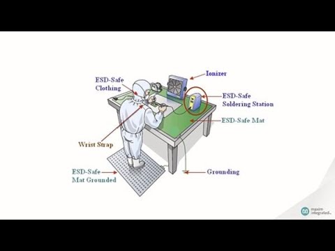
Vidéo de formation : Contexte ESD
Cette vidéo éducative neutre soutient le contexte de contrôle des ESD. Elle ne remplace pas la validation spécifique au produit décrite ci-dessus.
Guides associés
- Sélection de matériaux antistatiques ESD
- Stockage dissipatif vs stockage conductif
- Liste de contrôle de demande de devis pour emballages ESD
Foire aux questions
Quand un insert est-il préférable à un nouveau plateau ?
Un insert peut être utile pour des volumes plus faibles, des kits mixtes ou un encombrement extérieur établi, à condition que la stabilité et la manipulation restent acceptables. La règle finale doit être documentée pour le dispositif spécifique, l'installation et le plan de contrôle.
Quel jeu faut-il prévoir pour une poche ?
Il n'y a pas de valeur universelle. Le jeu dépend des tolérances des composants, des éléments vulnérables, de la méthode de préhension et du mouvement attendu lors de la manipulation. La règle finale doit être documentée pour le dispositif spécifique, l'installation et le plan de contrôle.
Les inserts peuvent-ils être remplacés indépendamment ?
Ils le peuvent lorsque l'interface a été conçue pour le démontage et que le matériau et la géométrie de remplacement restent contrôlés. La règle finale doit être documentée pour le dispositif, l'installation et le plan de contrôle spécifiques.
Les inserts nécessitent-ils une vérification ESD ?
Oui lorsqu'ils entrent en contact ou entourent de près les articles sensibles. Testez le système d'emballage assemblé sous le contrôle du plan de contrôle. La règle finale doit être documentée pour le dispositif spécifique, l'installation et le plan de contrôle.
Qu'est-ce qui doit figurer dans la demande de devis (RFQ) ?
Inclure les schémas des composants, les échantillons, l'orientation, la quantité, l'interface du plateau, le rôle du matériau, les besoins de nettoyage, le parcours prévu et les critères de validation. La règle finale doit être documentée pour le dispositif, l'installation et le plan de contrôle spécifiques.
Références faisant autorité
- Association ESD : Les fondamentaux des ESD
- NASA-STD-8739.6B : Contrôle des décharges électrostatiques
- Programme de qualification du travail de la NASA
Note d'application : Les limites finales et les intervalles de vérification doivent respecter le programme approuvé de l'installation, les exigences relatives aux dispositifs, les normes en vigueur, les instructions du fabricant et les méthodes d'essai qualifiées. Ce guide est une aide à l'approvisionnement et à la planification des processus, et non un substitut à ces documents contrôlés.

Laisser un commentaire