- Blog
An SMT ESD magazine rack can create a controlled board queue between printer and pick-and-place, but only after the line owner defines the board state, maximum dwell, traceability, and escalation rule. A rack protects handling flow; it does not authorize boards to wait beyond a process limit.
Use this guide to place a physical buffer deliberately rather than treating every open floor area as storage. The ESD Magazine Rack category is the product-family starting point, while the line layout and board state remain your process team’s decision.

Part 1. Define a controlled buffer point
A buffer point is a named place where boards may wait under defined conditions. It needs an entry trigger, a maximum quantity, a board-state label, an owner, and an action when the limit is reached. Without those controls, a magazine rack becomes untracked WIP rather than a useful decoupling point.
For example, a short queue may protect pick-and-place utilization during a brief downstream interruption. It cannot by itself correct a persistent feeder, printer, or inspection constraint. The escalation rule should expose that constraint instead of letting the queue grow.
Part 2. Map line boundaries
The printer-to-placement boundary deserves special care because the board’s process state can change while it waits. Confirm the permitted wait condition with the paste, process, and quality owners; do not use a physical rack to bypass a documented timing rule.
| Boundary | Useful rack role | Control to define |
|---|---|---|
| Before printing | Bare-board staging | Revision, orientation, and quantity |
| Printer to pick-and-place | Short controlled exception queue | Board state, maximum dwell, traceability |
| Pick-and-place to inspection | Handling queue | Program status and first-in-first-out rule |
| Inspection to rework | Segregated hold | Defect status and disposition owner |
| End of line to downstream handoff | Protected transport buffer | Pack-out state and destination |
For broader handling context, see the anti-static magazine rack buffering guide. It does not replace a line-specific process map.
Part 3. Size capacity and layout

Capacity should follow an allowed time window and an observed board rate, then be reduced for a practical escalation margin. Do not select a large rack simply because floor space allows it; excess slots can hide a growing delay.
| Capacity input | What to record | Why it matters |
|---|---|---|
| Board rate | Boards or panels per minute | Converts time allowance into quantity |
| Maximum permitted dwell | Process-owner value | Sets the queue ceiling |
| Slot count and pitch | Actual rack configuration | Defines physical capacity |
| Orientation | Entry and exit direction | Supports first-in-first-out handling |
| Access path | Operator and cart clearance | Prevents unsafe bypasses |
| Escalation threshold | Quantity or time trigger | Makes bottlenecks visible |
Place the rack where an operator can load and unload without crossing a machine service zone. If the rack will interface with a loader, treat outer dimensions, guide position, handle clearance, and orientation as first-article checks.
Part 4. Protect board state
Every buffer needs a visible rule for what is allowed to enter. A bare board, printed board, placed board, rejected board, and rework board should not share an ambiguous queue. Use labels or a traceability record that identifies the stage, time, program revision, and next destination.
IPC-A-610 is assembly-quality context, not a layout specification. The relevant operational point is simple: quality and traceability controls stay with the manufacturing system when a board changes hands.
If the printer-to-placement interval becomes routine rather than exceptional, investigate the cause. Adding slots may mask material starvation, feeder setup, maintenance, or scheduling issues that require a different response.
Part 5. Check ESD and interfaces
Sanwei’s ESD Magazine Rack solution page states a 10^6–10^9 Ω range for its stated line. Pair that supplier statement with your own ESD program checks under IEC 61340-5-1 and ANSI/ESD S20.20.
At line acceptance, check slot pitch, guide opening, board-edge support, outer footprint, and any loader engagement feature. Measure or request documented resistance according to the agreed method, and repeat the check when material, cleaning method, or rack condition changes.
Part 6. Select a rack option
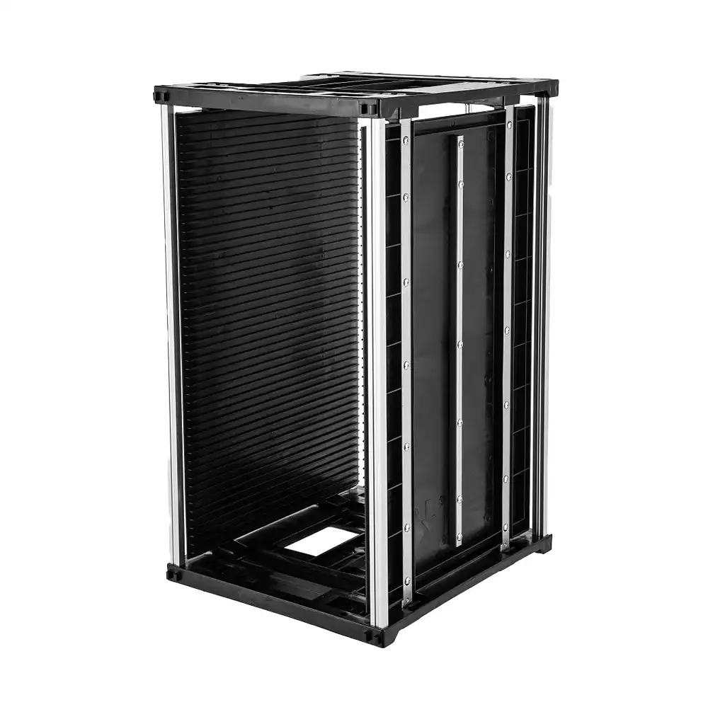
Start with the ESD Magazine Rack solution when you need to discuss pitch, heat duty, resistance evidence, or a custom layout. If the board envelope and interface review align, the 355(L)×320(W)×H mm ESD magazine rack is an appropriate product-recommendation starting point.
Fit Boundary
| Buyer situation | Suitable path | Avoid |
|---|---|---|
| Short, defined handling queue | Rack with labeled entry and exit | Unbounded WIP storage |
| Printer-to-placement queue | Process-approved dwell and traceability | Using the rack to bypass timing rules |
| Loader-connected buffer | First-article interface validation | Assuming a product photo proves fit |
| Reflow-adjacent queue | Confirm actual heat exposure | Assigning a heat grade without duty details |
For movable buffer locations during a format change, the portable rack line-changeover guide provides a related workflow. Send layout, board drawings, capacity rule, and quantity bands through Contact Sanwei for product matching.
FAQ
Where should PCB magazines be placed on an SMT line?
Place them at named handling boundaries with a defined entry condition, maximum quantity, owner, and exit rule. The exact location depends on board state and machine layout.
Can boards wait between printing and placement?
Only within the process window approved by the responsible team. The rack can hold a controlled queue, but it does not change paste, quality, or traceability requirements.
How many PCB buffer slots are needed?
Calculate capacity from the allowed dwell and board rate, then set an escalation threshold below the physical maximum. Validate the result during line trials.
What causes PCB magazines to jam in a loader?
Common causes include an incorrect outer envelope, guide position, orientation, handle clearance, slot geometry, or an interface feature that was not checked on the first article.
How should an ESD rack be checked on a line?
Confirm physical fit, board-edge support, slot configuration, and the agreed resistance-test evidence. Recheck after changes that can affect the rack or its handling environment.
Does a buffer solve a bottleneck?
It can absorb a short interruption, but it does not remove a recurring constraint. A persistent full rack should trigger investigation, not a larger rack purchase.

Leave a Reply