- Turbo
- Blog
Surface resistance and surface resistivity describe related measurements, but they should not be treated as interchangeable purchasing specifications. Surface resistance is the resistance measured between defined contacts on a surface. Surface resistivity is a geometry-normalized surface property calculated using an applicable electrode arrangement and method. A result written in ohms and a result described as ohms per square may therefore answer different questions. Before accepting an ESD material, ask what was measured, how the contacts were arranged, and which requirement the result is intended to satisfy.
This distinction matters when comparing trays, bins, work surfaces and handheld testers. Two reports can show similar numbers while using different contact arrangements or conditioning. This guide focuses on interpreting the quantities and writing a clear specification. For a practical measurement sequence, use the separate ESD surface tester measurement guide.
What surface resistance tells a buyer
Surface resistance describes the electrical resistance of the path established by the test contacts. The report needs to identify those contacts because their spacing, size and placement influence the measured path. Point-to-point resistance on a work surface, resistance between electrodes on a flat specimen, and resistance to a defined grounding connection are different arrangements. Simply labeling all three measurements as surface resistance removes information needed to interpret the result.
For purchasing, name the intended quantity in the specification and require the supplier to describe its setup. An acceptance requirement for one defined path should not silently be replaced by a convenient measurement elsewhere. On a molded bin, testing an accessible flat wall may help characterize that location, but it does not automatically establish the electrical behavior of every divider, lid, handle or connection in the assembled container.
What surface resistivity adds
Surface resistivity relates a measured resistance to a defined surface geometry. The familiar description ohms per square expresses a normalized surface quantity; it does not mean that a square has to be one particular physical size. The conversion depends on the arrangement assumed by the method. It should not be made by changing the unit label on a resistance reading or by applying an unexplained correction factor from another instrument.
In a simple ideal rectangular conducting sheet, a geometry model can relate resistance to the path length and width. Real ESD materials may have nonuniform coatings, textured surfaces, curved walls or contact effects that make that simple model inappropriate. A laboratory should identify the applicable geometry factor and calculation when reporting resistivity. Buyers should retain the original measured result as well as the derived quantity so the relationship remains reviewable.
A comparison table for specifications
| Quantity | What the result describes | İstenmesi gereken delil |
|---|---|---|
| Surface resistance | Resistance along the path between defined surface contacts | Contact arrangement, spacing, settings and units |
| Surface resistivity | Surface quantity normalized using an applicable geometry | Electrode method, factor, measured resistance and calculation |
| Resistance to ground | Resistance from a defined location to its grounding connection | Test location, installed connections and complete path |
| Volume resistivity | Normalized through-material measurement | Specimen construction, dimensions and applicable method |
Use this table as a terminology check rather than a universal acceptance standard. A numerical limit still needs to come from the applicable product requirement, customer specification or controlled test method. If a report omits its contact geometry, request clarification before ranking one material above another. This is especially important when one quotation lists surface resistivity and another lists resistance to ground: the names indicate different evidence, even when both are relevant to an ESD control plan.
Why electrode geometry changes the comparison
An electrode system determines where current enters and leaves the specimen. The contact area and the distance between contacts affect the path being examined. A concentric arrangement and two separated contacts should not be assumed to produce directly comparable raw values. Contact pressure, surface texture and the ability to seat the electrodes consistently can also affect repeatability. A small molded pocket may not accommodate the same arrangement used on a broad flat panel.
Ask the laboratory how it handles a specimen that is smaller than the intended electrode footprint. Cutting a coupon, selecting a different electrode or using an adapted fixture may be reasonable under an appropriate method, but the change must be disclosed. A flat coupon result and an assembled-product result should remain separate records. This prevents an attractive material number from hiding a contact problem in the finished product.
Keep volume properties separate
Volume resistance examines a path through a material, rather than the surface path discussed here. Volume resistivity normalizes a volume measurement using the relevant dimensions and geometry. A supplier’s statement that a polymer is conductive does not establish which quantity was measured. A coating may influence a surface measurement differently from a bulk-filled material, and a layered specimen may require additional interpretation.
For incoming review, mark each result with its quantity and method before comparing values. Do not convert surface resistivity into volume resistivity without an applicable physical model and supporting measurements. A material data sheet can help explain the formulation, but the acceptance record should describe the actual supplied construction, including coating, substrate and thickness where they matter. That is particularly useful when evaluating an alternative supplier or a revised finish.
Conditions that belong beside the result
Temperature, humidity, conditioning history and specimen cleanliness can influence measurements. The report should identify the conditions used rather than present the value as a timeless property of every item. A result measured after controlled conditioning should not be assumed to predict a recently cleaned part, a wet part or an item used in a different environment. Record the test condition and the intended operating condition separately.
The applicable test method should determine the voltage, electrification time and conditioning procedure. Do not select these settings only because they make the reading easier to obtain. If a supplier changes a setting between lots, ask why and whether the new results remain comparable. Also distinguish a displayed numerical result from a range indication or an out-of-range result; these carry different levels of detail for procurement decisions.
An illustrative calculation and its limits
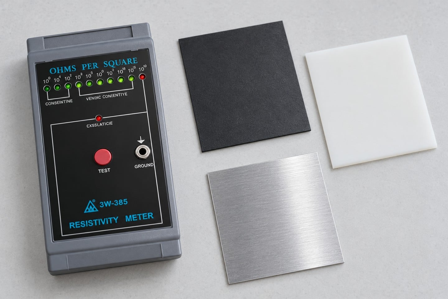
The Georgia Tech lecture on resistivity and sheet resistance explains the ideal L/W relationship used below. This geometric teaching example does not replace the acceptance procedure for a molded ESD product.
For an ideal homogeneous rectangular sheet with full-width parallel contacts, a simplified model is R = rho_s × L/W, where R is measured resistance in ohms, rho_s is sheet or surface resistivity in ohms per square, and L and W are the path length and width expressed in the same length unit. Rearranging gives rho_s = R × W/L. This example explains the role of geometry; it is not a procedure for certifying an ESD tray or assigning a material classification.
Suppose an illustrative specimen measures 20 megohms, with an idealized path length twice its width. Under that model, the normalized value is 10 megohms per square. These are hypothetical numbers, not SWESD test results or acceptance limits. The conversion is useful only if the model, contact arrangement and material assumptions apply. An unknown probe layout, curved wall or nonuniform coating invalidates a casual use of this calculation.
Reading a supplier report without losing context
Start with the product identity, specimen location and revision. Then identify whether the reported quantity is resistance, resistivity or resistance to a grounding connection. Read the method and electrode description before examining the number. Finally check the stated conditions and the acceptance requirement. This order makes it harder to mistake a convenient headline value for evidence that the actual use case has been tested.
Request a clarification when a report uses mixed terminology, lists a unit without naming the quantity, or reports only pass without the underlying measurements. A satisfactory response should explain the measurement and any conversion. It should not merely replace the heading on the original document. For a complete document review, use the surface resistivity testing background alongside the report fields in your purchase specification.
Choosing a tester and planning acceptance
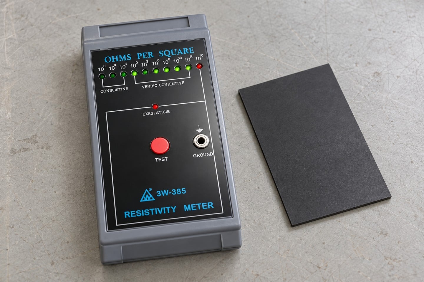
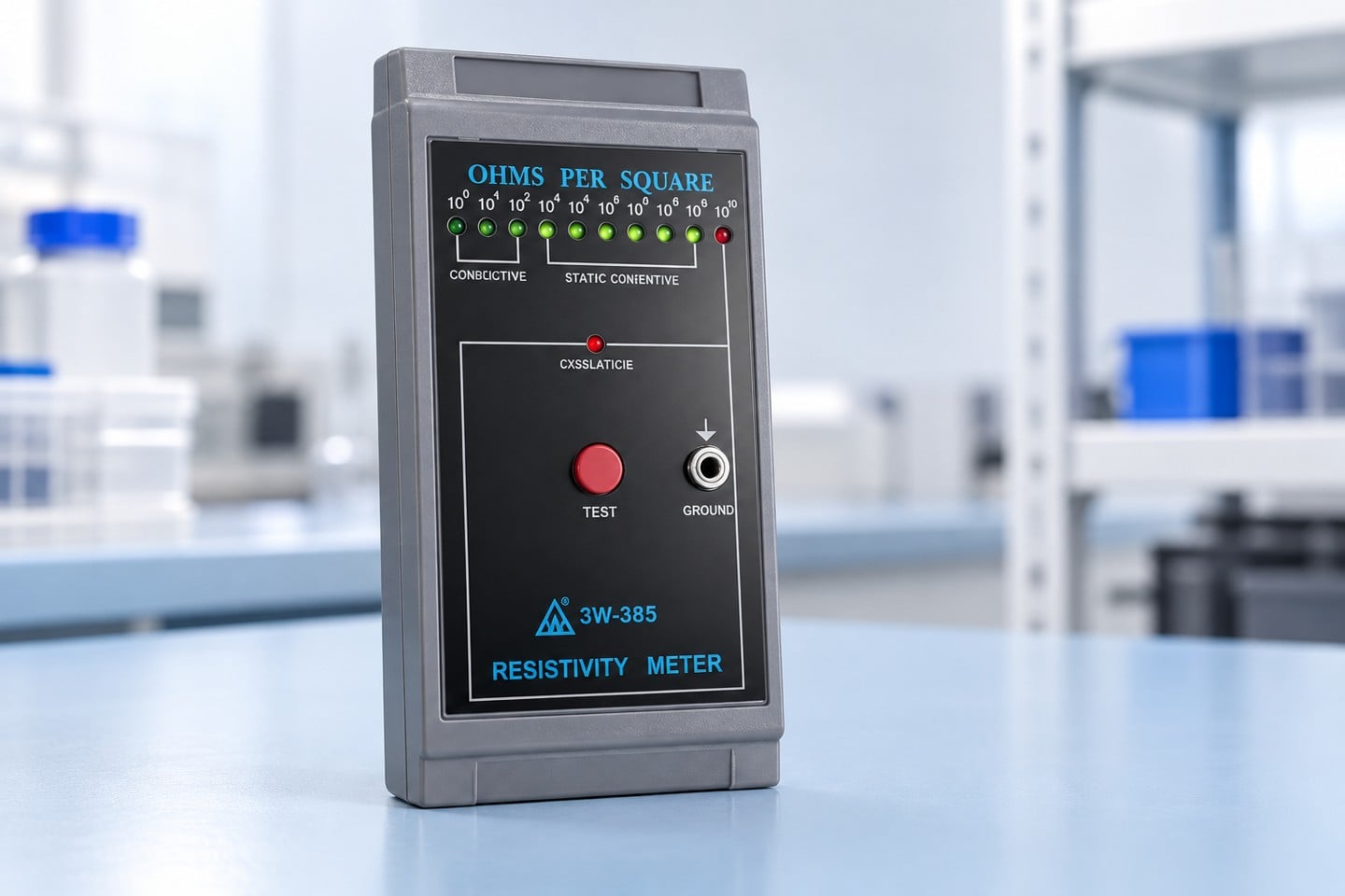
The SWESD surface resistance tester is a product starting point for a measurement-equipment inquiry. Confirm the exact supplied model, supported measurement arrangements, accessories, range, resolution and calibration documentation before deciding that it can perform your required method. A faceplate label or a catalog photograph does not establish all of these capabilities, and this guide makes no additional performance claim for the product.
Prepare the intended specimen dimensions, test quantity, method reference, expected measurement range and reporting needs for the inquiry. Ask who will approve the setup and how routine verification will be recorded. The tester calibration guide covers a different part of the process: maintaining confidence in the instrument rather than choosing the meaning of the reported material property. Mechanical fit, electrostatic function and instrument suitability should each have their own evidence.
Further learning and practical review
The EOS/ESD Association material-control overview places resistance measurements within a broader control program. Its guidance supports treating a material result as one part of the process rather than a blanket guarantee against damage. The NIST measurement traceability guidance is useful when evaluating the measurement evidence supporting a reported value; traceability alone does not decide whether a product suits your application.
Use the educational video to review basic electrostatic concepts, then return to the controlled method for the actual acceptance test. Assign one person to resolve terminology before sample testing begins. Agree on the reporting template, retain the unconverted readings, and identify which assembled-product checks are needed after material approval. This modest preparation often prevents a larger dispute after delivery, when suppliers and buyers discover that they were comparing different quantities.
Sık sorulan sorular
Can I rename an ohm reading as ohms per square?
No. A resistivity result requires an applicable geometry and conversion. Keep the raw measurement and identify the calculation rather than changing the label.
Does one square mean one square centimeter?
No. Ohms per square describes a normalized sheet quantity. It does not prescribe a single physical square size for every method.
Are point-to-point resistance and resistance to ground the same?
No. They examine different defined paths. Record the arrangement and use the measurement required by the relevant acceptance specification.
Can I compare reports with different humidity conditions?
Treat them as different conditions until the responsible technical reviewer establishes a valid comparison. Request the conditioning and measurement details.
Does a favorable surface value guarantee protection for a finished tray?
No. The result supports only the stated sample and measurement scope. Application, assembled-product behavior and other required properties need their own evidence.

Bir Yorum Bırakın