- Blog
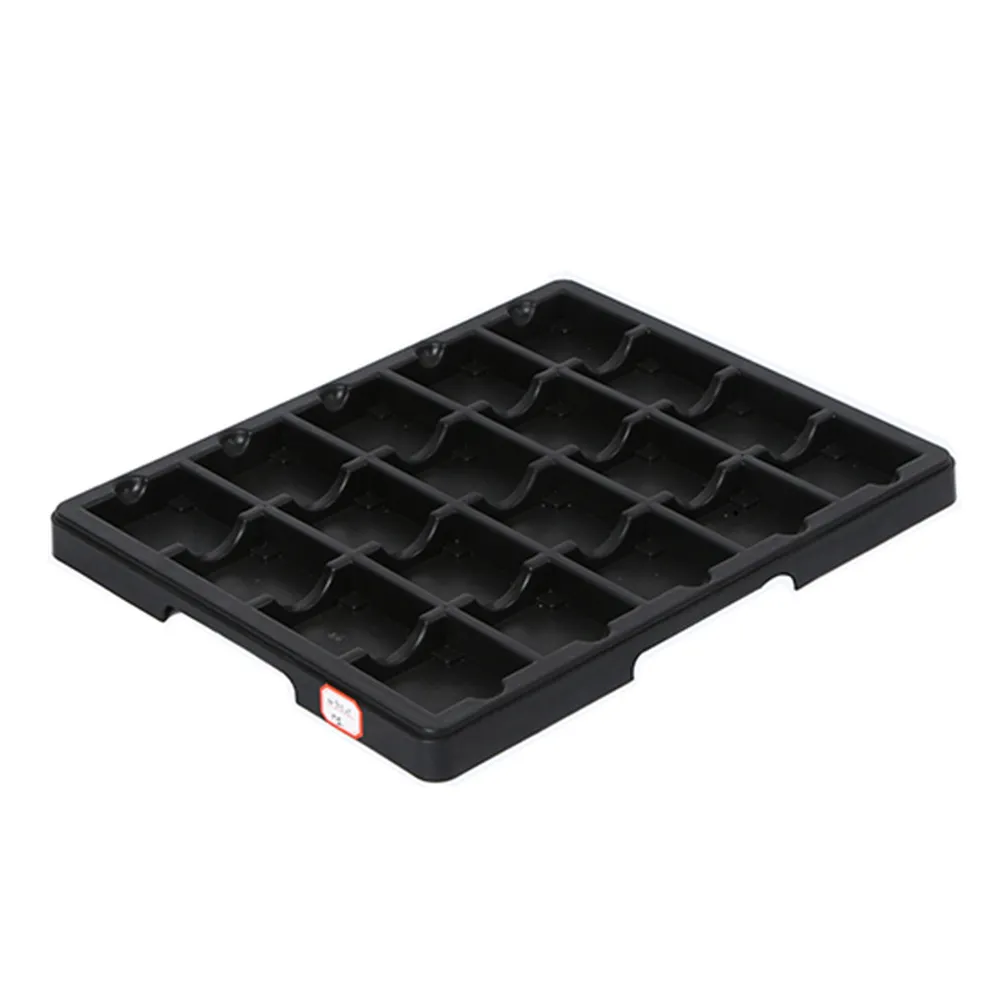
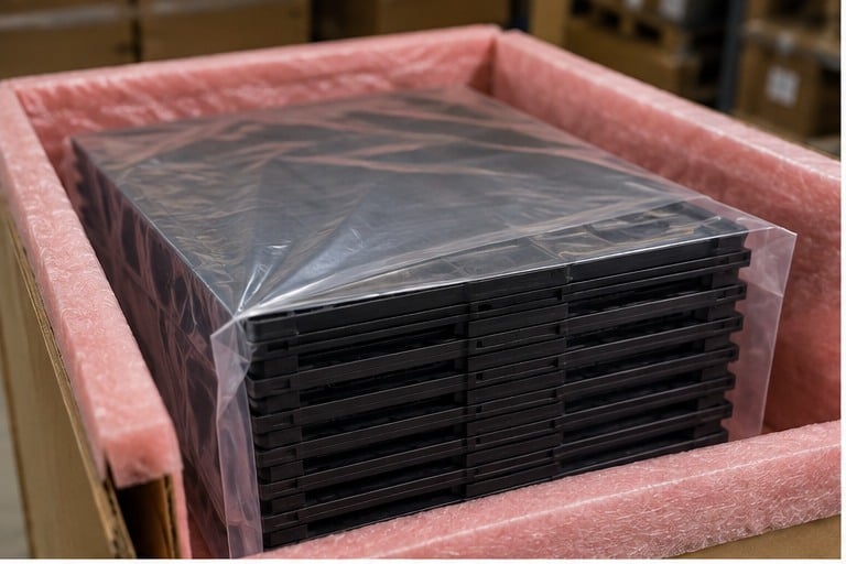
Choose an ESD tray with grids from the PCB or item envelope first, then verify that the chosen cell layout leaves the required clearance for edges, connectors, loading, and removal. A published grid count is only a starting point. The selected model, drawing, ESD evidence, and sample-use criteria should be confirmed before release.
La ESD Tray category lists the available tray family, including a grid-tray product. For a line-side context beyond grid sizing, see the related ESD tray staging guide.
Part 1. Define the board-to-grid job
Grid trays are useful when a team needs visible, repeatable separation of defined PCBs or electronic items at a workstation, kitting point, inspection bench, or controlled handoff. The decision starts with the job: one board per cell, a defined component kit per cell, or a clearly labeled set of identical items.
Do not use the grid count as the job definition. A tray with many cells may be wrong for a board with edge connectors, a tall assembly, or a removal motion that needs more finger clearance. Conversely, a larger cell can waste space or weaken the intended lot-segregation rule if several unrelated items share it.
An ESD tray is not a substitute for a PCB magazine rack when boards must be buffered between process machines. The PCB tray overview can help frame a tray role, while a magazine-rack review is needed for machine-to-machine PCB buffering.
| Operating question | Buyer-defined answer |
|---|---|
| What occupies one cell? | One board, one panel, one component kit, or another defined item |
| Where is the tray used? | Kitting, line-side staging, inspection, rework, or controlled handoff |
| How is the item handled? | Loaded by hand, removed by hand, or presented to a defined process |
| What must stay separate? | Lots, work orders, revision states, or item types |
| What does the cell not prove? | Load capability, transport qualification, or universal mechanical protection |
Part 2. Measure the complete PCB envelope
Measure the item that actually enters and leaves the cell, not only the bare board outline. Include the maximum board length, width, thickness, edge hardware, connectors, soldered features, labels, and any allowed packaging or handling aid. A drawing or clear marked-up photograph is more useful than a nominal board name.
The required orientation belongs on the same record. A board that enters long-edge first may need a different cell shape and access clearance than one lifted vertically. If an operator uses gloves, tweezers, or a fixture, record the space that action requires.
| Worksheet field | What to record | Why it changes grid selection |
|---|---|---|
| Overall envelope | Maximum length, width, thickness, and protrusions | Establishes the actual item space |
| Contact restrictions | Edges, components, connectors, or areas that must not touch a wall | Prevents a nominal fit from becoming an interference fit |
| Orientation | Entry direction, stored face, and removal direction | Determines usable clearance and label position |
| Cell allocation | One item/lot rule for each cell | Supports segregation and count control |
| Handling method | Hand, glove, tool, or fixture interaction | Defines access space for loading and removal |
| Workstation interface | Bench, cart, rack, or fixture location | Confirms the tray footprint and workflow fit |
Leave clearance values to the buyer’s drawing, process need, and sample review. There is no safe universal clearance value for every PCB, connector arrangement, operator method, or grid tray.
Part 3. Select a published grid-layout starting point
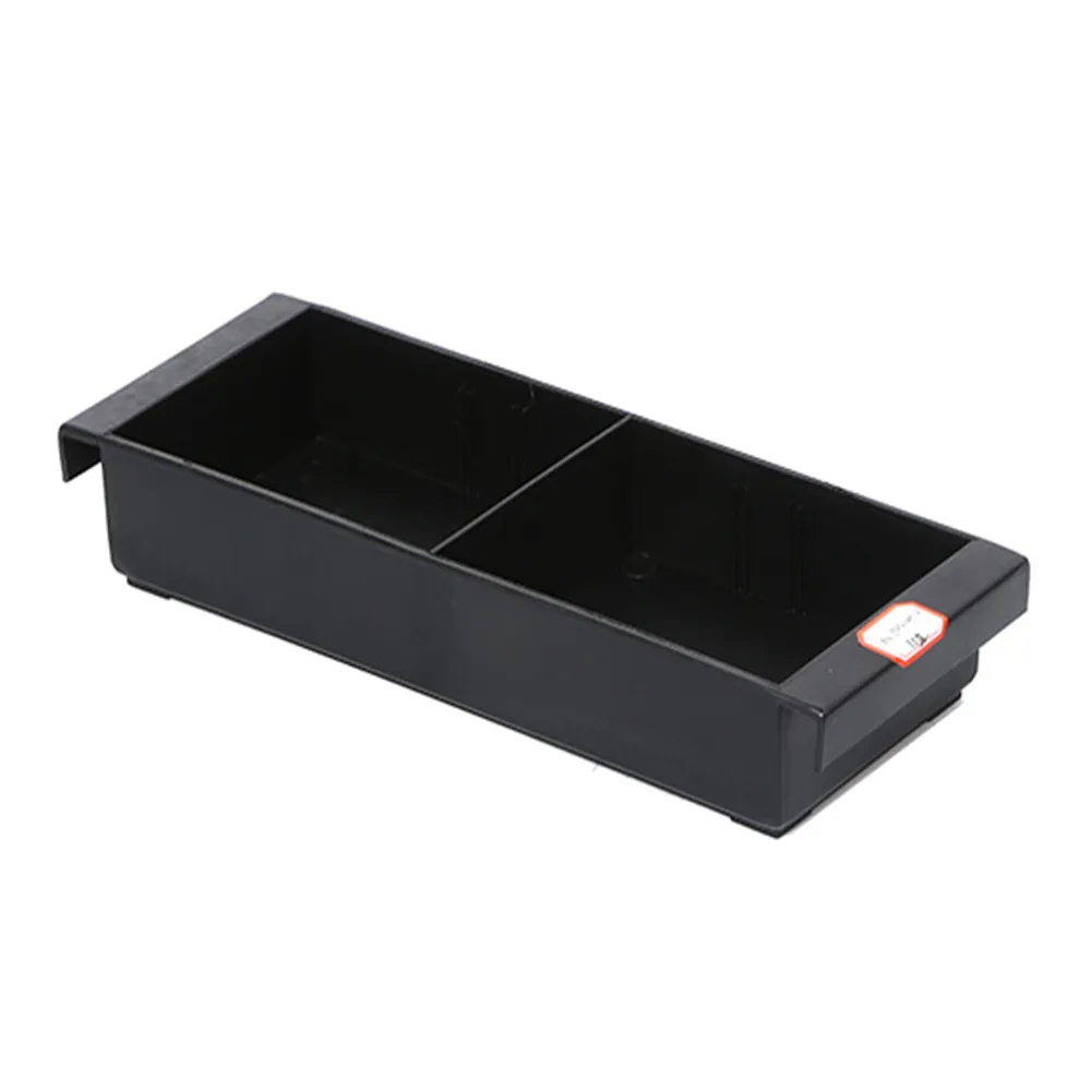
The published Sanwei ESD Tray With Grids page shows multiple named model rows rather than one universal tray. Use it to identify a possible starting row only after the envelope worksheet is complete.
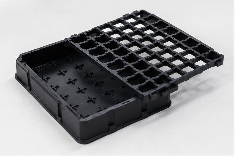
For example, the page identifies model 3W-9805112 as a detachable 70-grid configuration. The same published row states external dimensions of 457 × 312 × 39 mm and internal dimensions of 417 × 292 × 30 mm. That information is specific to that model; it does not establish the usable dimensions or acceptance of a different layout.
Other listed rows show ten-, twelve-, twenty-, or eighty-grid arrangements. Select between them by comparing the relevant current model row with the item drawing and handling motion, then ask for confirmation for the selected request.
| Published-page observation | Selection implication | Do not infer |
|---|---|---|
| Multiple named model rows | Start a comparison at the row closest to the required envelope and allocation | That all grid layouts share the same cell size |
| Detachable 70-grid description for 3W-9805112 | Ask whether the requested configuration is that named model and how it will be used | That every grid is detachable |
| Different grid counts across rows | Review cell allocation, orientation, and clearance model by model | That more cells automatically mean a better PCB fit |
| Published external and internal dimensions | Compare them with the tray footprint and the required usable area | That published dimensions prove fixture or workstation compatibility |
Part 4. Check clearance, access, and handling motion
A board can fit within a cell outline and still be unsuitable for the operation. Connector shells, tall components, edge tabs, test points, or a required grip path can clash with a divider wall. Review the full item in its stored orientation.
Use a sample or a controlled mock-up to observe loading, seating, removal, and return. Record whether the item stays in its allocated cell, whether the operator can remove it without contacting restricted areas, and whether the tray can be placed at the intended station without a conflict.
| Sample-use check | Accept when the buyer’s criterion is met |
|---|---|
| Load | The item enters its assigned cell in the required orientation |
| Seat | No prohibited edge, connector, or component contact is observed |
| Remove | The defined operator method has the required access |
| Identify | The item/lot rule remains clear before and after handling |
| Place | The tray fits the intended workstation or fixture interface |
| Repeat | The process owner can repeat the action under the intended operating conditions |
Do not convert an image, a nominal grid count, or an adjacent model’s dimensions into a clearance promise. The buyer’s item and handling route determine the acceptance decision.
Part 5. Set orientation, segregation, and workstation rules
Once the physical fit is confirmed, make the layout operable. Assign a stored orientation, cell address or location rule, and a label field that connects the physical cell to the buyer’s lot, work order, or process status. The tray can support those controls, but it does not establish traceability on its own.
Mixed board sizes can share a tray only when the cell allocation and identification rule remain unambiguous. If a different board requires a different orientation or larger access area, assign it to a separate defined cell pattern or a separate tray rather than relying on operator memory.
At the workstation, verify the tray’s placement, pick direction, and return location. A grid layout that works on a flat inspection bench may not work on a cart, shelf, or fixture with limited reach.
| Control | Buyer should define |
|---|---|
| Orientation | Which edge or face is stored in the named direction |
| Cell identity | How each cell is associated with an item, lot, or status |
| Label content | The fields required by the buyer’s process |
| Changeover | How empty, obsolete, or mixed-content cells are handled |
| Station interface | Where the tray sits and how it is retrieved or returned |
Part 6. Confirm ESD evidence and configuration boundaries
The product page uses ESD and anti-static terminology and publishes model-level static-index information for listed rows. Request the electrical requirement, test method, test conditions, measurement locations, and evidence format required by the buyer’s ESD-control program for the specific quoted configuration.
CEI 61340-5-1 et ESD Association standards information provide program context. They do not certify a particular grid tray, prove that a selected board is protected in a particular workflow, or replace the buyer’s facility controls.
Keep unverified attributes outside the selection decision. Confirm model-specific material construction, temperature capability, load suitability, cleaning compatibility, price, MOQ, and lead time directly for the selected request rather than inferring them from a product family, photo, or grid count.
Part 7. Build the RFQ and sample-use review
An effective RFQ lets the supplier evaluate a defined arrangement instead of guessing from “PCB grid tray.” Attach the worksheet and identify the published model row, if one is being considered. State which questions still need confirmation.
| RFQ or sample-use input | Buyer should provide |
|---|---|
| Item drawing | Maximum envelope, protrusions, contact restrictions, and relevant photos |
| Grid intent | Item or lot per cell, desired orientation, and proposed layout |
| Handling route | Loading, removal, station interface, and return action |
| Identification | Required label fields and cell/lot allocation rule |
| Configuration review | Relevant published model row, requested accessories, and open questions |
| ESD evidence | Required electrical target, method, conditions, locations, and evidence format |
| Sample acceptance | Scenarios, observers, pass criteria, and exceptions to record |
| Quantity planning | Quantity bands after model and configuration confirmation |
Product recommendation
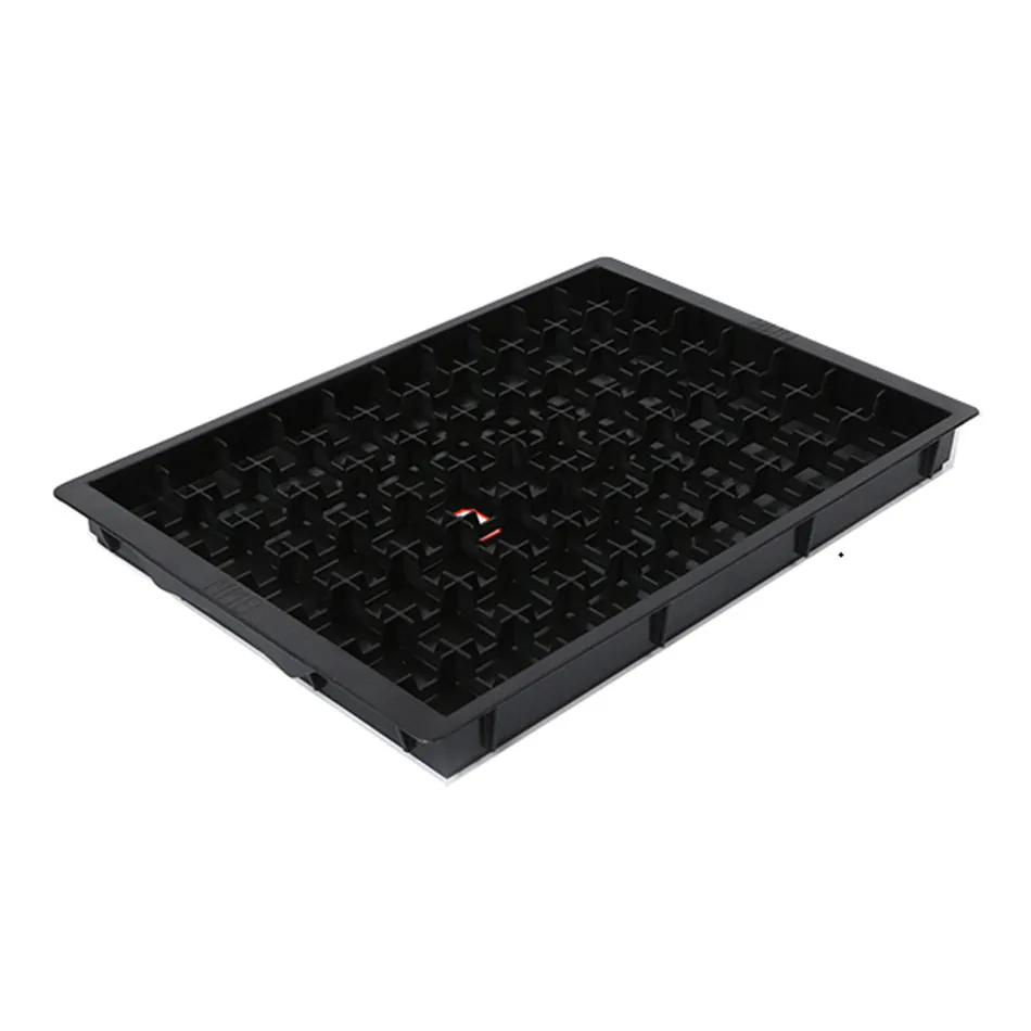
Use the Sanwei ESD Tray With Grids page as the product-discovery route when a dimensioned PCB or item drawing and an intended grid allocation are available. Send the worksheet through Contact Sanwei to confirm the selected model, configuration, and evidence available for the quote.
Fit Boundary
| Buyer situation | Suitable path | Avoid |
|---|---|---|
| Defined board or item per cell | Compare the drawing and handling route with a published grid-tray row | Selecting only by the total grid count |
| Multiple lots at one workstation | Define cell allocation and the buyer’s label rule | Treating a grid wall as traceability by itself |
| PCB buffering between machines | Review a magazine rack and the machine-flow requirement | Substituting a shallow grid tray for a PCB buffer without process review |
| ESD requirement | Request evidence for the selected configuration under the buyer’s method | Treating a category name or image as acceptance evidence |
| Unknown fit or access | Run a sample-use review | Assuming any cell that contains the outline is acceptable |
FAQ
What is an ESD tray with grids used for?
It can organize defined PCBs or electronic items into visible, separated cells for a stated staging, kitting, inspection, or handoff task. The buyer should define what occupies each cell and how the item is handled.
How should I measure a PCB for a grid tray?
Record the maximum length, width, thickness, connectors, edge hardware, tall features, required orientation, and insertion/removal motion. Use the complete envelope rather than the bare board outline.
Should a PCB fit tightly in a grid cell?
No universal tightness rule applies. The cell should be reviewed against the buyer’s required clearance, restricted-contact areas, and handling method in a sample-use check.
Can one grid tray hold different PCB sizes?
It may, if the buyer defines a clear cell allocation, orientation, and identification rule for every item. Do not assume a shared tray is suitable when board envelopes or access needs conflict.
Does Sanwei list different grid-tray layouts?
Yes. The published ESD Tray With Grids page shows multiple named model rows and different grid arrangements. Confirm the current selected model and configuration for the quotation.
What ESD information should be requested?
Request the electrical requirement, test method, conditions, measurement locations, and evidence format required by the buyer’s ESD-control program for the selected configuration.
Do grid trays replace a magazine rack?
No. A grid tray can support defined shallow staging or segregation. A magazine rack should be reviewed when the process needs controlled PCB buffering between machines.
What should be checked on a tray sample?
Check loading, seating, removal, prohibited-contact areas, orientation, cell identity, workstation placement, and repeatability against the buyer’s documented acceptance criteria.
Laisser un commentaire