- Blog
Un rack de magazines ESD pour CMS peut créer une file d'attente de cartes contrôlée entre l'imprimante et la machine de placement, mais seulement après que le responsable de la ligne a défini l'état de la carte, le temps de séjour maximum, la traçabilité et la règle d'escalade. Un rack protège le flux de manutention ; il n'autorise pas les cartes à attendre au-delà d'une limite de processus.
Utilisez ce guide pour placer délibérément un tampon physique plutôt que de traiter chaque zone de plancher ouvert comme un espace de stockage. Le Catégorie de présentoirs de magazines ESD est le point de départ de la famille de produits, tandis que la disposition de la ligne et l'état des cartes restent la décision de votre équipe de processus.

Partie 1. Définir un point tampon contrôlé
Un point de tampon est un emplacement nommé où les cartes peuvent attendre dans des conditions définies. Il nécessite un déclencheur d'entrée, une quantité maximale, une étiquette d'état de carte, un propriétaire et une action lorsque la limite est atteinte. Sans ces contrôles, un présentoir devient un en-cours non suivi plutôt qu'un point de découplage utile.
Par exemple, une file d'attente courte peut protéger l'utilisation du système de prélèvement et de pose lors d'une brève interruption en aval. Elle ne peut pas à elle seule corriger une contrainte persistante au niveau d'un chargeur, d'une imprimeuse ou d'un poste d'inspection. La règle d'escalade doit mettre en évidence cette contrainte au lieu de laisser la file d'attente s'allonger.
Partie 2. Délimiter les lignes
La limite entre l'imprimante et le placement mérite une attention particulière car l'état du processus de la carte peut changer pendant qu'elle attend. Confirmez la condition d'attente autorisée avec les responsables de la sérigraphie, du processus et de la qualité ; n'utilisez pas de rack physique pour contourner une règle de temps documentée.
| Limite | Rôle de rack utile | Commande à définir |
|---|---|---|
| Avant l'impression | Mise en place de cartes nues | Révision, orientation et quantité |
| Imprimante vers machine de placement | File d'attente d'exceptions courte et contrôlée | État du plateau, temps de séjour maximal, traçabilité |
| Prise et placement vers l'inspection | Gestion des files d'attente | État du programme et règle du premier entré, premier sorti |
| Inspection pour retouche | Cale séparée | Statut du défaut et responsable de la disposition |
| Transfert de fin de ligne vers l'aval | Tampon de transport protégé | État de déménagement et destination |
Pour un contexte de manipulation plus large, voir le guide de mise en mémoire tampon pour magasin antistatique. Il ne remplace pas une cartographie de processus spécifique à la ligne.
Partie 3. Capacité de taille et agencement

La capacité doit respecter une plage horaire autorisée et un taux d'embarquement observé, puis être réduite pour une marge d'escalade pratique. Ne choisissez pas un grand rack simplement parce que l'espace au sol le permet ; des emplacements excédentaires peuvent masquer un retard croissant.
| Saisie de la capacité | Quoi enregistrer | Pourquoi c'est important |
|---|---|---|
| Tarif de pension | Panches ou panneaux par minute | Convertit l'allocation de temps en quantité |
| Temps d'arrêt maximal autorisé | Valeur du propriétaire de processus | Définit le plafond de la file d'attente |
| Nombre d'encoches et pas | Configuration actuelle du rack | Définit la capacité physique |
| Orientation | Sens d'entrée et de sortie | Prend en charge le traitement premier entré, premier sorti |
| Chemin d'accès | Dégagement de l'opérateur et du chariot | Empêche les contournements non sécurisés |
| Seuil d'escalade | Déclencheur par quantité ou par temps | Rend les goulets d'étranglement visibles |
Placez le présentoir de manière à ce qu'un opérateur puisse charger et décharger sans traverser une zone de service de la machine. Si le présentoir doit interagir avec un chargeur, traitez les dimensions extérieures, la position du guide, le dégagement de la poignée et l'orientation comme des contrôles de premier article.
Partie 4. Protéger l'état du plateau
Chaque tampon a besoin d'une règle visible concernant ce qui est autorisé à y entrer. Une carte nue, une carte imprimée, une carte posée, une carte rejetée et une carte de retouche ne doivent pas partager une file d'attente ambiguë. Utilisez des étiquettes ou un enregistrement de traçabilité qui identifie l'étape, l'heure, la révision du programme et la destination suivante.
IPC-A-610 est un contexte de qualité d'assemblage, et non une spécification de disposition. Le point opérationnel pertinent est simple : les contrôles de qualité et de traçabilité restent avec le système de fabrication lorsqu'une carte change de mains.
Si l'intervalle entre l'impression et le placement devient routinier plutôt qu'exceptionnel, enquêtez sur la cause. L'ajout de emplacements peut masquer des problèmes de pénurie de matériaux, de configuration des chargeurs, de maintenance ou de planification qui nécessitent une réponse différente.
Partie 5. Vérification de la DES et des interfaces
Sanwei Page de solution de rack à magazines ESD indique une plage de 10^6 à 10^9 Ω pour sa ligne déclarée. Associez cette déclaration du fournisseur à vos propres contrôles du programme ESD sous CEI 61340-5-1 et ANSI/ESD S20.20.
Lors de l'acceptation de la ligne, vérifier le pas des encoches, l'ouverture des guides, le support des bords de carte, l'empreinte extérieure et tout dispositif d'engagement du chargeur. Mesurer ou demander une résistance documentée selon la méthode convenue, et répéter la vérification en cas de modification du matériau, de la méthode de nettoyage ou de l'état du rack.
Partie 6. Sélectionnez une option de rack
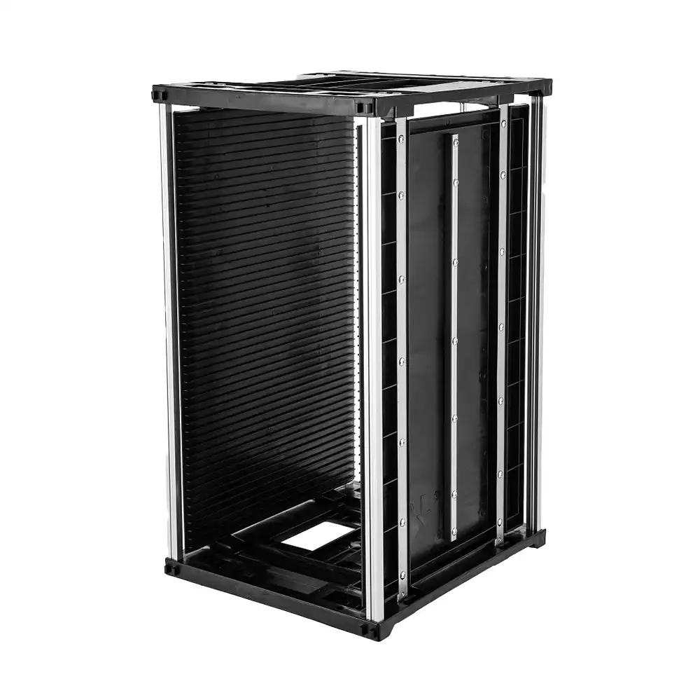
Commencez par le Solution de présentoir de magazines ESD lorsque vous devez discuter du pas, de la charge thermique, des preuves de résistance ou d'une disposition personnalisée. Si l'encombrement de la carte et l'examen de l'interface correspondent, Magasin de cartes ESD 355(L)×320(l)×H mm constitue un point de départ approprié pour la recommandation de produits.
Ajuster la limite
| Situation de l'acheteur | Chemin approprié | Éviter |
|---|---|---|
| File d'attente de manutention courte et bien définie | Rack avec entrée et sortie étiquetées | Stockage d'en-cours illimité |
| File d'attente « de l'imprimante au placement » | Temps de séjour et traçabilité approuvés par le processus | Utilisation du rack pour contourner les règles de synchronisation |
| Tampon relié au chargeur | Validation de l'interface de premier article | En supposant qu'une photo de produit prouve la conformité |
| File d'attente adjacente au reflow | Confirmer l'exposition réelle à la chaleur | Attribution d’un niveau de chaleur sans précisions sur les tâches |
Pour les emplacements de tampon mobiles lors d'un changement de format, le guide de changement de série pour rack portable fournit un flux de travail connexe. Envoyez la disposition, les dessins de cartes, la règle de capacité et les bandes de quantité Contacter Sanwei pour la correspondance de produits.
FAQ
Où faut-il placer les magazines de circuits imprimés sur une ligne d'assemblage SMT ?
Placez-les à des limites de manutention nommées avec une condition d'entrée définie, une quantité maximale, un propriétaire et une règle de sortie. L'emplacement exact dépend de l'état du plateau et de la disposition de la machine.
Les circuits imprimés peuvent-ils attendre entre l'impression et le placement ?
Uniquement dans la fenêtre de processus approuvée par l'équipe responsable. Le rack peut contenir une file d'attente contrôlée, mais il ne modifie pas les exigences en matière de pâte, de qualité ou de traçabilité.
Combien de logements de mémoire tampon PCB sont nécessaires ?
Calculez la capacité à partir du temps de stationnement autorisé et du taux d'embarquement, puis définissez un seuil d'alerte en deçà du maximum physique. Validez le résultat lors des essais de ligne.
Quelles sont les causes du blocage des magasins de PCB dans un chargeur ?
Parmi les causes courantes, on peut citer une enveloppe extérieure incorrecte, une position ou une orientation incorrecte du guide, un jeu insuffisant au niveau de la poignée, une géométrie de fente inadaptée ou une caractéristique d'interface qui n'a pas été vérifiée sur le premier article.
Comment faut-il vérifier un rack ESD sur une ligne ?
Vérifiez l'état physique, le maintien des bords de la carte, la configuration des emplacements et les résultats des tests de résistance convenus. Effectuez une nouvelle vérification après toute modification susceptible d'affecter le rack ou son environnement d'exploitation.
Un tampon résout-il un goulet d'étranglement ?
Cela peut permettre de pallier une brève interruption, mais cela ne résout pas un problème récurrent. Un rack constamment saturé devrait donner lieu à une enquête, et non à l'achat d'un rack plus grand.

Laisser un commentaire