- Turbo
- Blog
Stacking ESD trays safely requires more than placing one tray on another. A stable stack depends on a compatible rim-and-base interface, flat trays, controlled load distribution, a defined maximum stack height, and handling rules that keep the stack aligned from storage through transport. Nesting is different: empty trays fit partly inside one another to save return-storage space, but loaded trays normally need a positive stacking interface that protects the parts below. Buyers should validate the complete loaded stack, not infer performance from tray color or surface resistance alone.
Stacking, nesting and simple piling are different
A stackable tray transfers load through intended contact points around its rim, corners or molded rails. A nestable tray rotates or changes orientation so empty units occupy less vertical space. A tray that merely has a flat base may sit on another tray, but that does not prove it is a controlled stack. The distinction matters because an unsupported base can bow into the parts below, while a poorly located rim can slide during cart movement.
Start the specification by naming the operating mode: loaded stacking, empty nesting, or both. If both are required, document the orientation that changes the mode and add a visible poka-yoke feature or work instruction. Operators should not need to guess whether a tray must be rotated 180 degrees.
| Mode | Main purpose | Interface to verify | Typical risk |
|---|---|---|---|
| Loaded stacking | Protect parts while using vertical space | Rim, corner and base engagement | Bow, slip or excessive load on lower trays |
| Empty nesting | Reduce return and storage volume | Taper, stops and release clearance | Jamming or surface abrasion |
| Simple piling | Temporary placement only | No defined positive interface | Uncontrolled movement and contact |
Begin with the real product and process envelope
Record the tray outside dimensions, usable inside dimensions, empty mass, material, temperature range, and the condition in which electrical performance is specified. Then record the part mass, quantity per tray, center of gravity, protrusion above the rim, and any lid, liner or separator. A stack that is stable when empty can behave differently when the load is high, off-center or concentrated in a few cavities.
Also measure the environment: shelf depth, cart deck, conveyor guides, lift clearance, aisle turns and packaging carton. The nominal tray footprint alone is not enough. A raised label holder, bowed wall or overhanging liner can change the effective envelope and catch on adjacent equipment.
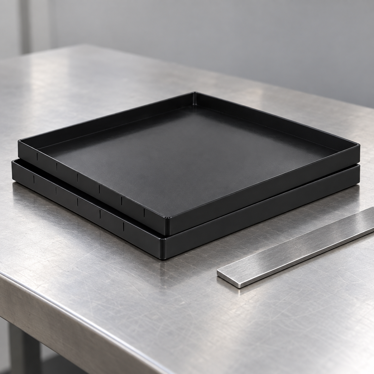
Check rim alignment and support paths
Place representative trays on a verified flat surface. Check all four corners and the long sides for rocking, gaps, burrs, warpage or local damage. Then stack two empty units and apply light horizontal pressure in each direction. The upper tray should locate consistently without riding on a label, liner or component. Repeat with production-representative loads because the support path may change as the base deflects.
Do not use one successful pair as evidence for a production batch. Sample trays from different cavities, lots and ages. Include cleaned trays and units that have completed realistic handling cycles. If a supplier uses several tools for one size, record the tool or cavity identity where practical.
Set stack height from evidence, not convenience
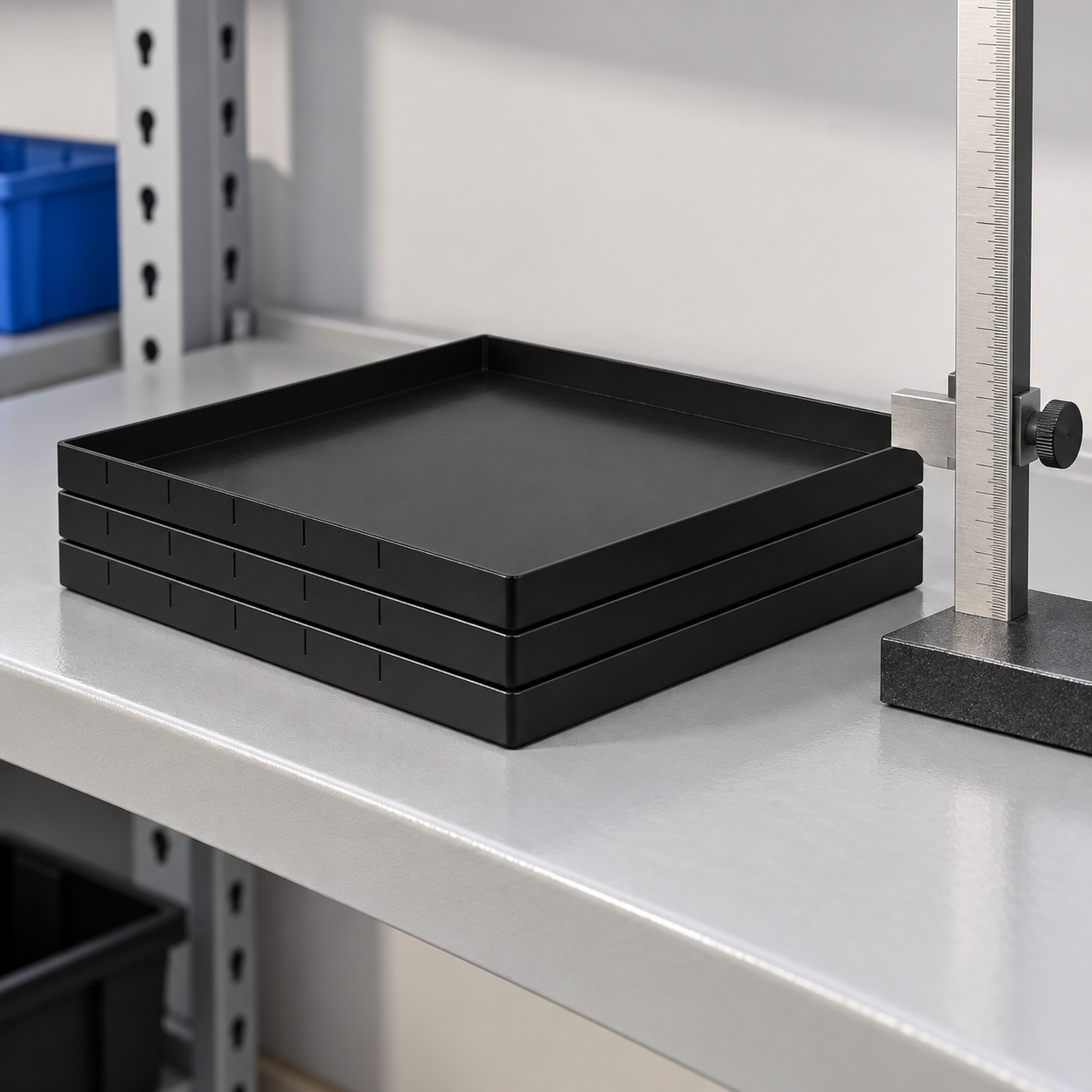
There is no universal safe number of ESD trays in a stack. The limit depends on tray geometry, resin system, temperature, load pattern, dwell time, surface condition, cart acceleration and the consequences of failure. Define a temporary engineering limit, test it, and reduce it when the handling route introduces greater shock, vibration or human reach risk.
A practical validation uses at least three conditions: normal load, foreseeable worst-case load distribution, and an intentionally small alignment error. Observe leaning, permanent set, rim damage, contact with parts below and release after dwell. Test the loaded stack on the actual shelf or cart, then repeat after movement. Shipping validation should follow the selected distribution test plan rather than a workshop-only demonstration; the International Safe Transit Association test-procedure overview explains how distribution hazards are organized.
Separate mechanical suitability from ESD protection
Mechanical stability does not establish electrostatic performance. A tray can stack perfectly and still be unsuitable for the item or protection zone. Conversely, a material described as static dissipative does not automatically have enough stiffness or creep resistance for a tall loaded stack. Treat electrical classification, physical protection and contamination control as separate verification items.
The EOS/ESD Association explains the system context for protecting susceptible items in its ESD fundamentals. Its ANSI/ESD S541 overview describes packaging materials used to protect ESD-sensitive items. Use the applicable current standard, customer requirements and measured material data when approving a tray.
Design the workflow around the approved stack
Mark the maximum loaded stack quantity on the traveler, shelf standard or reusable label rather than relying on memory. Define whether mixed part numbers are prohibited, whether the top tray requires a cover, and where incomplete stacks wait. A stack should have one identity at the handling-unit level while retaining traceability to the trays or lots inside.
Train handlers to lift from the bottom, keep the stack level and split stacks before they obstruct vision or exceed the approved manual-handling method. Never use stretch wrap or straps so tightly that tray walls deform. If a cart has lips or guides, confirm they restrain the bottom tray without concentrating force on one corner.
Plan empty-tray nesting without creating damage
Nesting saves space only if trays release predictably. Specify the nesting direction, nesting pitch and maximum empty nested quantity. Check that surfaces do not scrape labels, generate debris or lock together after cleaning and drying. Provide a separator or rack if operators otherwise pry trays apart with tools.
Keep loaded and empty-return areas visually distinct. A nested empty tray should never be inserted into a loaded stack because its deeper travel may contact components. Where rotation changes the mode, add a simple orientation cue and confirm it remains readable after repeated cleaning.
Receiving and periodic inspection checklist
- Confirm part number, revision, material declaration and approved supplier.
- Measure the footprint, rim height and stack pitch on a representative sample.
- Inspect flatness, corners, rims, labels and contact surfaces.
- Verify loaded engagement and clearance above the product.
- Run the approved movement, dwell and distribution tests.
- Quarantine cracked, bowed, contaminated or poorly locating trays.
- Revalidate after a material, tool, geometry, liner or cleaning-process change.
For purchasing, request drawings and samples before production approval. Include load distribution, stack quantity, dwell time, storage temperature, cart or conveyor interface, label zone, cleaning method and electrical requirements in the RFQ. The NASA workmanship standard portal for NASA-STD-8739.6 is also a useful example of why packaging and handling controls need documented workmanship requirements rather than assumptions.
Turn the validation into a controlled specification
A useful approval record states exactly what was tested. Photograph the tray orientation, load pattern, shelf or cart and any cover or liner. Record the sample quantity, conditioning time, observation points and acceptance criteria. Useful criteria include no tray-to-part contact, no disengaged corner, no permanent lean, no visible crack, no label interference and no unacceptable permanent set after unloading. Avoid a vague result such as “stack test passed,” because another team cannot reproduce it.
Give the approved configuration a revision and link it to the purchasing drawing and work instruction. If two tray revisions fit together but have different stack pitches, identify whether mixed-revision stacks are allowed. During a pilot run, ask operators to record difficult separation, rocking and unexpected contact. Those observations often reveal practical problems that a short bench check misses.
How this connects to SWESD tray selection
Benutzen Sie SWESD ESD tray range as the product starting point, then provide the actual part, load and process envelope for confirmation. The broader anti-static component tray guide explains tray roles. Review ESD tray material selection, tray load-capacity validation, and liner fit and contamination control as separate decisions. This prevents a mechanically convenient stack from hiding an electrical, dimensional or cleanliness mismatch.
Further learning: why ESD controls must work as a system

This EOS/ESD Association lecture gives neutral background on electrostatic-discharge controls. It supports the system context; the article’s mechanical stacking checks remain necessary.
Häufig gestellte Fragen
How many ESD trays can be stacked?
There is no universal number. Set the limit from the specific tray, loaded weight and distribution, dwell time, temperature, handling route and validation results.
Is a nestable tray automatically stackable when loaded?
No. Nesting is normally a space-saving mode for empty trays. Loaded stacking requires a verified support and locating interface.
Can tray color prove ESD performance?
No. Color can support visual management, but electrical behavior requires the applicable material specification and verification.
Should labels sit between stacked trays?
No label or holder should interrupt the approved load path or force the trays out of alignment. Reserve a label zone outside the engagement interface.
When should stack validation be repeated?
Repeat it after changes to material, tooling, geometry, load, liner, label, cleaning process, handling equipment or distribution route.
Schreiben Sie eine Antwort