- Turbo
- Blog
Conductive vs Static-Dissipative JEDEC Trays is a purchasing and validation problem: the aim is to choose the required electrical behavior from device risk and grounding conditions rather than treating conductive as automatically safer. A reliable decision starts with the protected device and its complete route, then converts the search term into measurable drawing, sample and receiving requirements. There is no universal material, tolerance, reuse count or test value that safely fits every program.
Decision Summary for conductive jedec trays
| Decision area | Define before quotation | Evidence to request |
|---|---|---|
| Control function | Low charging, dissipation, grounding or shielding | Define the actual hazard and route |
| Resistance evidence | Method, electrodes, voltage and conditioning | Compare results only under the same setup |
| Ground path | Contact between tray, equipment and facility ground | Test the assembled use condition |
| Device interaction | Exposed conductors and discharge energy | Obtain ESD-program review |
Use the table as an RFQ discussion guide, not as a substitute for controlled values. Final limits should come from current device drawings, equipment interfaces, the facility ESD program, supplier documentation and qualified trials. When a number is not yet known, state the functional risk and agree a prototype test instead of copying a limit from an unrelated tray.
1. Control function: Turn the Requirement into Evidence
For conductive jedec trays, the buyer must define low charging, dissipation, grounding or shielding. This point controls whether the tray can choose the required electrical behavior from device risk and grounding conditions rather than treating conductive as automatically safer. Write the requirement against the actual device, route and equipment rather than a generic tray description. Name the responsible drawing or work instruction, the condition in which the characteristic applies, and who approves an exception.
The practical verification is to define the actual hazard and route. Begin with identified samples from the proposed production material and tooling. Record sample quantity, lot or cavity, conditioning, equipment, method and result. Include both normal and credible worst-case conditions. A pass on one convenient sample is useful for development, but it is not evidence that production variation is controlled.
Ask the supplier to explain which input variables can change this result. Depending on the characteristic, these may include resin or sheet lot, additive level, molding or forming settings, cooling, trimming, storage, cleaning and previous use. Convert important variables into incoming evidence, periodic checks or formal change notification. This makes the requirement auditable and prevents a catalog promise from becoming the only acceptance basis.
2. Resistance evidence: Turn the Requirement into Evidence
For conductive jedec trays, the buyer must define method, electrodes, voltage and conditioning. This point controls whether the tray can choose the required electrical behavior from device risk and grounding conditions rather than treating conductive as automatically safer. Write the requirement against the actual device, route and equipment rather than a generic tray description. Name the responsible drawing or work instruction, the condition in which the characteristic applies, and who approves an exception.
The practical verification is to compare results only under the same setup. Begin with identified samples from the proposed production material and tooling. Record sample quantity, lot or cavity, conditioning, equipment, method and result. Include both normal and credible worst-case conditions. A pass on one convenient sample is useful for development, but it is not evidence that production variation is controlled.
Ask the supplier to explain which input variables can change this result. Depending on the characteristic, these may include resin or sheet lot, additive level, molding or forming settings, cooling, trimming, storage, cleaning and previous use. Convert important variables into incoming evidence, periodic checks or formal change notification. This makes the requirement auditable and prevents a catalog promise from becoming the only acceptance basis.
3. Ground path: Turn the Requirement into Evidence
For conductive jedec trays, the buyer must define contact between tray, equipment and facility ground. This point controls whether the tray can choose the required electrical behavior from device risk and grounding conditions rather than treating conductive as automatically safer. Write the requirement against the actual device, route and equipment rather than a generic tray description. Name the responsible drawing or work instruction, the condition in which the characteristic applies, and who approves an exception.
The practical verification is to test the assembled use condition. Begin with identified samples from the proposed production material and tooling. Record sample quantity, lot or cavity, conditioning, equipment, method and result. Include both normal and credible worst-case conditions. A pass on one convenient sample is useful for development, but it is not evidence that production variation is controlled.
Ask the supplier to explain which input variables can change this result. Depending on the characteristic, these may include resin or sheet lot, additive level, molding or forming settings, cooling, trimming, storage, cleaning and previous use. Convert important variables into incoming evidence, periodic checks or formal change notification. This makes the requirement auditable and prevents a catalog promise from becoming the only acceptance basis.
4. Device interaction: Turn the Requirement into Evidence
For conductive jedec trays, the buyer must define exposed conductors and discharge energy. This point controls whether the tray can choose the required electrical behavior from device risk and grounding conditions rather than treating conductive as automatically safer. Write the requirement against the actual device, route and equipment rather than a generic tray description. Name the responsible drawing or work instruction, the condition in which the characteristic applies, and who approves an exception.
The practical verification is to obtain esd-program review. Begin with identified samples from the proposed production material and tooling. Record sample quantity, lot or cavity, conditioning, equipment, method and result. Include both normal and credible worst-case conditions. A pass on one convenient sample is useful for development, but it is not evidence that production variation is controlled.
Ask the supplier to explain which input variables can change this result. Depending on the characteristic, these may include resin or sheet lot, additive level, molding or forming settings, cooling, trimming, storage, cleaning and previous use. Convert important variables into incoming evidence, periodic checks or formal change notification. This makes the requirement auditable and prevents a catalog promise from becoming the only acceptance basis.
Prototype and Production Approval
Approve the proposal in gates. First review the device revision, orientation, allowed contact, route, equipment and packaging stack. Next inspect identified first articles and verify the four decision areas above. Then load representative minimum and maximum devices, build the real stack, apply covers or restraints, and run the normal handling sequence. Include cleaning, heat, labels, storage and shipment only where they belong to the actual route.
Keep the approved drawing, material or construction identity, sample lot, photographs, raw results, deviations and sign-off together. Receiving inspection should check identity before sampling, separate lots, inspect critical features with the approved datum and method, and quarantine failures before they mix with accepted inventory. Sampling depth follows risk and supplier history; it should not be invented in a blog or purchase note.
Failures That the Control Plan Must Prevent
Failure 1: Selecting the lowest resistance value without considering the system
This shortcut can release trays that look acceptable but fail during handling. Contain the affected lot, identify where the assumption entered the specification, and compare the tray with the controlled device and process requirements. Repeat the relevant dimensional, functional or electrical check under documented conditions. Record the disposition so the same issue can be recognized at receiving and during reuse.
Failure 2: Testing a flat coupon instead of the tray contact surfaces
This shortcut can release trays that look acceptable but fail during handling. Contain the affected lot, identify where the assumption entered the specification, and compare the tray with the controlled device and process requirements. Repeat the relevant dimensional, functional or electrical check under documented conditions. Record the disposition so the same issue can be recognized at receiving and during reuse.
Failure 3: Confusing low charging with resistance classification
This shortcut can release trays that look acceptable but fail during handling. Contain the affected lot, identify where the assumption entered the specification, and compare the tray with the controlled device and process requirements. Repeat the relevant dimensional, functional or electrical check under documented conditions. Record the disposition so the same issue can be recognized at receiving and during reuse.
RFQ and Supplier Checklist
- Controlled device drawing, samples, orientation and surfaces that may contact the pocket.
- Tray quantity, stack quantity, cover, restraint, outer packaging and equipment interfaces.
- The four topic-specific decision areas and the exact evidence expected for each.
- Material or construction identity, restricted substances, cleaning and environmental exposure.
- First-article quantity, production-lot traceability, inspection method and retention records.
- Change notification for material, additive, coating, tool, cavity, site, process or subcontractor.
- Reuse inspection, obsolete-label control, cleaning instructions and retirement criteria where applicable.
Start the commercial discussion from SWESD’s IC tray product page. For adjacent decisions, consult the JEDEC tray dimensions guide, custom IC tray RFQ guide and semiconductor shipping tray guide. These pages support planning; the controlled project documents remain decisive.
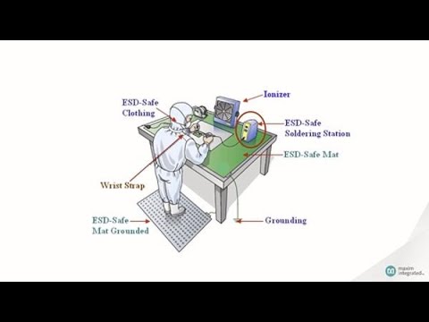
Educational Video: ESD Context
This neutral manufacturer video explains electrostatic-discharge fundamentals. It is supplementary and does not set project-specific tray limits.
Frequently Asked Questions
Is conductive always better than dissipative?
No. The correct behavior depends on device, contact, ground path and control plan. The approved answer should identify the applicable device, tray revision, route and evidence so that purchasing and production use the same rule.
Can color identify the class?
No. Measure using the approved method. The approved answer should identify the applicable device, tray revision, route and evidence so that purchasing and production use the same rule.
Does a conductive tray provide shielding?
Not automatically; shielding performance is a separate packaging property and test question. The approved answer should identify the applicable device, tray revision, route and evidence so that purchasing and production use the same rule.
Should every pocket be measured?
Use a justified sampling plan that includes relevant surfaces and process variation. The approved answer should identify the applicable device, tray revision, route and evidence so that purchasing and production use the same rule.
What should a report include?
Material and lot, conditioning, method, instrument, electrodes, voltage, locations, results and limits. The approved answer should identify the applicable device, tray revision, route and evidence so that purchasing and production use the same rule.
Authoritative References
- EOS/ESD Association: packaging and material-handling fundamentals
- NASA-STD-8739.6B: Electrostatic Discharge Control
- JEDEC JEP95: registered and standard mechanical outlines
Application boundary: Final dimensions, electrical limits, temperature exposure, inspection frequency and disposition rules must follow current controlled drawings, standards, manufacturer information and the facility quality and ESD systems.


Leave a Reply