- เทอร์โบ
- บล็อก
PCB magazine rack conveyor compatibility requires a match between the magazine, loader or unloader, board geometry and machine settings. Overall rack dimensions alone cannot establish compatibility. Confirm the base support, locating features, slot pitch, board exit height, pushing path and clearance, then run representative boards through the intended interface under an approved trial. An ESD marking adds a separate electrical requirement; it does not prove mechanical fit. This guide focuses on accepting a magazine at an existing line interface, rather than selecting an entire automated handling system or assuming that every rack works with every machine.
Start with the actual receiving machine
Identify the loader or unloader model, revision and installed magazine options. A conveyor carries individual boards; the magazine usually interfaces with a machine that indexes slots and transfers boards onto or from that conveyor. Treat these as different interfaces. Ask the machine owner for the accepted magazine drawing, board limits, locating arrangement and setup procedure. An advertised conveyor width range does not tell you whether the magazine base fits its loader.
Take photographs of the empty receiving position and record the surfaces that support and locate the magazine. Include rails, stops, clamps, sensors and any projections that could meet its frame. Identify which machine adjustments operators may change and which are service settings. A rack that can be forced into position after moving a fixed stop has not demonstrated approved compatibility. Keep guards and interlocks operating throughout the trial, and follow the equipment manufacturer's safe setup instructions.
Compare drawings before comparing samples
Build a comparison sheet using the controlled magazine and machine drawings. Record external length, width and height, base profile, support footprint, locating points, slot count, slot pitch and orientation. Use units consistently and note tolerances. Separate a nominal catalog measurement from a checked sample measurement. If the machine drawing gives a range, confirm that the rack remains within it across adjustment positions and manufacturing variation.
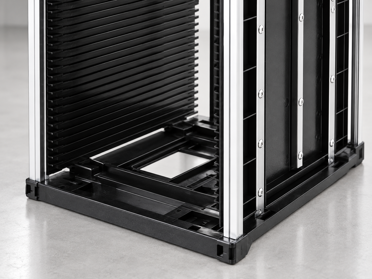
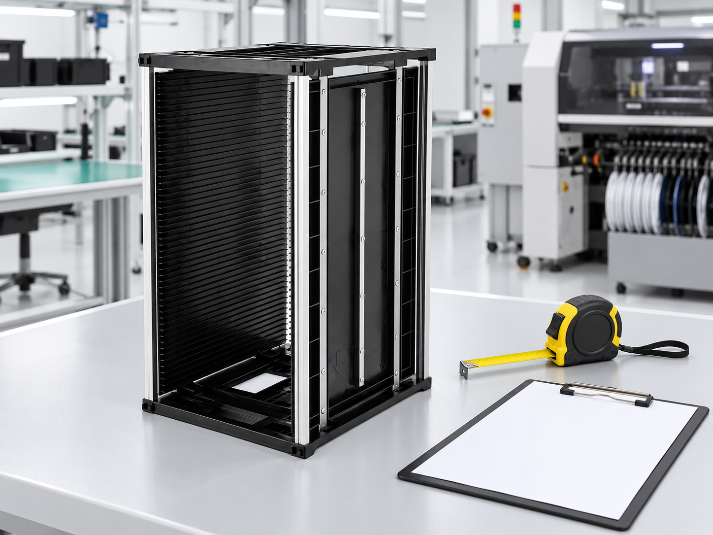
เดอะ illustrated SWESD magazine rack provides a real product reference for the frame and grooved panels shown here. Confirm the exact supplied model and dimensions with its controlled drawing. The photograph cannot establish slot tolerances, allowable load or machine certification. For the broader carrier selection process, see the anti-static magazine rack overview. This interface check adds acceptance details to that wider selection decision.
Follow the board from groove to conveyor
Trace the supported board edge as it leaves a slot, passes the transition and engages the conveyor rails. Check the vertical step, lateral alignment, free span and clearance around components. The magazine can sit correctly while the board catches at its exit. Inspect both the first and last usable slots because accumulated pitch error or a distorted panel may only appear at the ends. Do not infer full-range compatibility from one board in a middle slot.
Board thickness, panel size, edge finish and component overhang also matter. Use representative assemblies, including the permitted extremes, rather than only a smooth bare-board sample. Define the required support edge and any component keep-out area with the process owner. A pusher must act on a suitable part of the board without hitting an overhanging connector. The slot-width guide covers groove fit; here that fit must remain acceptable during transfer.
Verify indexing and orientation together
The magazine slot pitch and the loader's indexing recipe must agree. Record the starting slot, indexing direction, occupied-slot pattern and any deliberate skipped slots. Mixed board families can require different spacing for component clearance, but an operator should not create a new pitch recipe without approval. Mark the permitted orientation in the work instruction so an apparently symmetrical rack is not loaded backwards.
Check whether the machine detects a magazine, a board or an empty position, and where each sensor observes the assembly. Dark plastic, reflective metal and a projecting label may affect a particular sensor arrangement. Ask the equipment owner to validate detection using the actual rack and labels. This is an interface test, not a reason to bypass an alarm or cover a sensor. Record the expected response to an empty slot and the approved recovery sequence.
Use a compatibility acceptance table
| Interface | Check | Acceptance evidence |
|---|---|---|
| Magazine base | Support, stops and locating points | Controlled drawings and empty insertion trial |
| Slot indexing | Pitch, start position and occupied pattern | Approved recipe and first-to-last slot trial |
| Board transfer | Exit height, rail alignment and pusher clearance | Representative assembled board transfer without binding |
| Sensor operation | Magazine and board detection | Expected responses with actual labels and surface finish |
| ESD condition | Approved assembly properties and transfer boundary | Separate electrical verification under the site plan |
The table is a qualitative trial framework, not a universal set of dimensional limits. Numerical limits belong in the machine specification, rack drawing and approved process requirements. NIST measurement terminology provides a useful basis for keeping measurement conditions and repeatability clear. State the instrument, reference points and rack configuration so two inspectors can repeat the comparison instead of debating different measurement locations.
Run an empty trial before a loaded trial
Begin with an empty magazine and verify insertion, location, clamping and removal under the equipment's approved setup mode. Observe every support point. Look for rocking, interference and clamp movement that could distort the frame. Confirm that the rack can be removed without reaching into hazardous moving areas. If access is obstructed, stop and involve the machine owner; changing the carrier is preferable to normalizing unsafe handling.
Next use an approved test board and progress through the intended occupied slots. Observe entry and exit without forcing a board or increasing actuator force to hide binding. Record the recipe, rack revision, board type and trial result. A fault that disappears after manually lifting one corner still indicates an unresolved interface problem. Adjust only authorized setup variables, then repeat the relevant positions to show that the correction is reproducible.
Include production variation in the trial
Test the smallest and largest approved board sizes, relevant thickness extremes and components that create the most demanding clearance. Include a partly filled rack if production uses partial lots. A full evenly loaded magazine can behave differently from an uneven arrangement. Also check the widest approved panel adjustment because the base and grooves must stay aligned at that setting. These are project-specific conditions; this article does not assign a capacity to the pictured rack.
After repeated transfer cycles, examine edges for scuffing, grooves for damage and the adjustment mechanism for movement. Record where each fault occurs rather than summarizing everything as a jam. A consistent failure at one slot suggests a different cause from random failures after magazine exchange. Comparing those patterns helps distinguish groove defects, board variation, locating errors and inconsistent recipes without guessing at the machine's internal control logic.
Keep ESD approval separate from mechanical approval
The magazine, board handling path and surrounding work area belong in the site's ESD control plan. Verify relevant electrical properties and bonding arrangements using the approved method for the complete assembly. Do not assume a silver frame is grounded or that a black groove panel provides shielding. The EOS/ESD Association materials guidance distinguishes grounding, material behavior and protective packaging. Use those distinctions when assigning tests, without treating a mechanical fit trial as electrical qualification.
Review the transfer boundary as well. A rack accepted inside an EPA may need qualified packaging for movement outside it. Keep the mechanical acceptance record and electrical verification together, with each approved by its responsible owner. If replacement panels, wheels or labels change the assembly, reassess the affected requirements. The used-rack inspection guide describes condition checks before reuse; compatibility still needs the specific receiving machine.
Document exchange, recovery and supplier requirements
Specify who changes magazines, how the correct recipe is selected, how empty and full racks are distinguished and how a failed transfer is escalated. Keep the accepted rack model and orientation visible in the setup instruction. Avoid instructions such as “adjust until it runs,” which hide uncontrolled changes. The acceptance record should make a later replacement straightforward: the next rack must meet the same drawing and reproduce the approved transfer behavior.
Send suppliers the machine interface drawing, board envelope, component clearance, slot pattern, adjustment range, handling route and electrical requirements. Request a sample before committing to a batch and ask how dimensional revisions are communicated. Keep an accepted reference sample where practical. Record the approval scope explicitly: a successful trial on one loader does not approve all conveyors, every board family or future machine revisions. This boundary prevents a narrowly proven result from becoming an unsupported universal claim.
Decide how to handle a failed interface trial
Classify the failure before ordering another magazine. A base mismatch requires a drawing comparison; binding in one groove requires a condition check; an incorrect starting position requires a recipe review by the authorized owner. Keep the rejected sample identified and do not let it return to the production queue. If a supplier proposes a modification, request a revised drawing and repeat the affected checks. Record whether the change alters electrical properties, handling orientation or maintenance requirements. This creates a clear acceptance decision instead of a series of undocumented adjustments that cannot be reproduced on the next delivery.
Further learning: material handling systems
The NPTEL IIT Guwahati lecture below explains material handling systems as part of manufacturing automation. It provides context for the role of conveyors and transfer equipment; it does not certify the illustrated magazine or replace the receiving machine's instructions.

คำถามที่มักถูกถาม
Does matching external size prove compatibility?
No. Base location, slot indexing, board exit geometry, sensors and the approved machine setup must also match.
Does a conveyor width range specify the magazine size?
Not by itself. The magazine normally interfaces with a loader or unloader that requires its own accepted carrier drawing.
Which slots should be included in a trial?
Include the first and last usable positions and other representative slots under the approved occupied-slot pattern.
Can a successful mechanical trial prove ESD suitability?
No. Mechanical transfer and electrical suitability require separate checks within their respective approval scope.
What should a replacement rack reproduce?
It should meet the controlled drawing, approved orientation and setup, and reproduce the accepted transfer behavior for the specified boards.
โพสต์ล่าสุด
-
-
 How to Inspect Used PCB Magazine Racks Before Reuse05 ต.ค.,2026
 -
 ESD Magazine Rack Labels for PCB Lot Traceability05 ต.ค.,2026
แสดงความคิดเห็น