- 터보
- 블로그
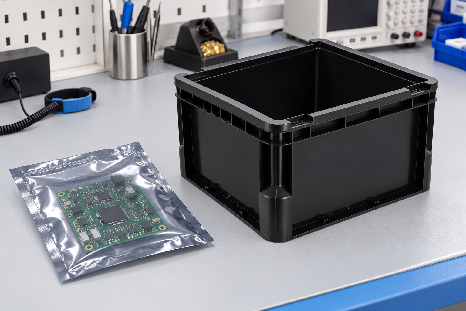
ESD bins for PCB assemblies should be selected around the board’s actual envelope, exposed components, allowed support points, packaging state and handling route. A bin that accepts a bare board dimension may still crush a tall connector, bend a populated panel or let one assembly strike another. Start with the released PCB assembly drawing and a representative loaded unit. Decide whether the board stays in a sealed protective pouch, rides in a custom tray or liner, or is handled bare inside an EPA. Then verify bin clearance, support, stacking and transport with the complete assembly. Do not infer protection from a black container alone.
Record the complete assembly envelope
Measure board length and width, maximum component height on both sides, connector overhang, weight, center of mass and any fragile protrusion. Include the packaging or insert that will travel with it. Use the latest assembly revision and check a worst-case sample, not only the bare PCB model. A cable tail or tall heat sink can make the effective envelope much larger than the board outline.
Mark approved support and handling zones. The bin, divider or inner tray should not press on solder joints, component bodies or sensitive contacts. If the assembly is sealed in a pouch, protect the pouch from sharp edges and leave room for the operator to lift it without folding the seal.
| Selection point | Input from PCB assembly | Physical check | Failure to avoid |
|---|---|---|---|
| Footprint | Board and package outline | Loaded fit at both ends | Board or pouch jammed against wall |
| Height | Tallest component and overhang | Clearance to lid, stack or shelf | Contact with connector |
| Support | Approved mechanical zones | Loaded deflection and contact | Point load on populated area |
| ESD | Device sensitivity and route | Packaging and EPA review | Container color treated as proof |
| 취급 | Pick, cart and shipment method | Lift, movement and recovery trial | Assembly sliding or falling |
This is a selection checklist. The actual dimensions and acceptance limits must come from the PCB assembly and approved handling plan.
Choose the protective layer before the outer bin
The outer bin may provide physical organization and load support. It does not automatically provide discharge shielding or moisture control. The EOS/ESD Association describes the difference between packaging inside and outside an EPA in its ESD fundamentals. Use the component’s sensitivity and route to choose the inner protective package.
For a moisture-sensitive device on the assembly, confirm whether the finished board itself has a controlled moisture or process requirement. The official IPC/JEDEC J-STD-033D contents describe moisture/reflow-sensitive device handling, but the applicability to a finished assembly must be determined by its process owner. Do not claim that an ordinary lidded bin acts as a dry pack.
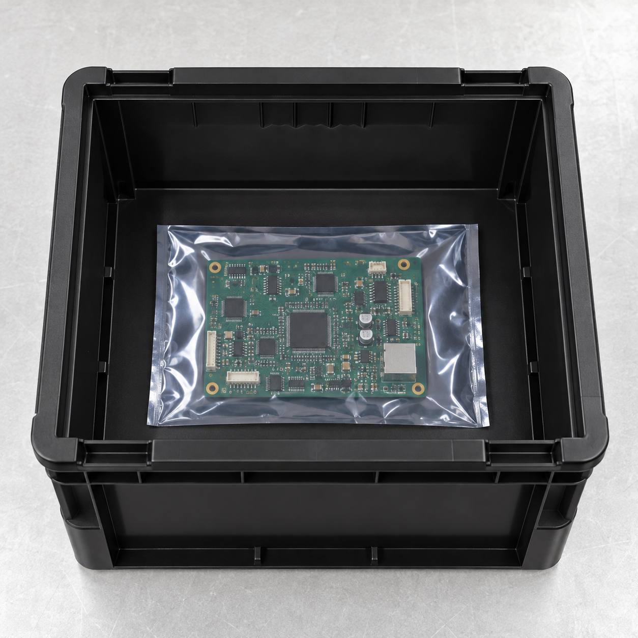
Evaluate the SWESD box geometry with a sample
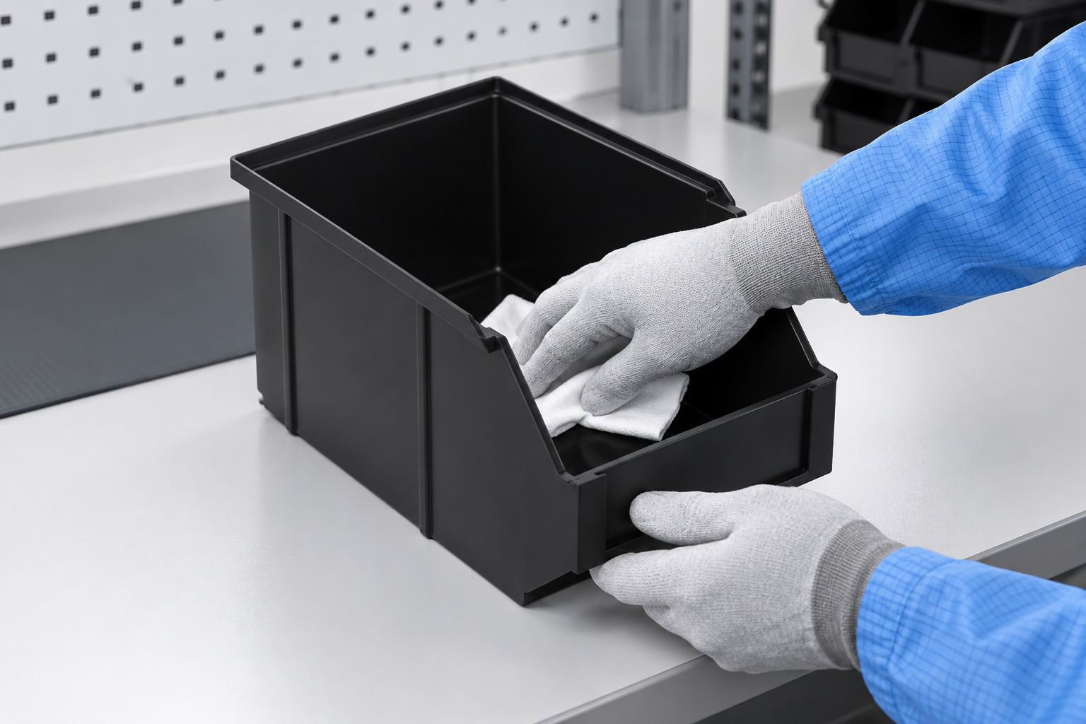
그 SWESD ESD circulation box is the product reference for these illustrations. It has a deep open-top rectangular form and reinforced walls visible in the original photograph. Confirm exact dimensions, resin, load and availability with the product supplier for a project. The rendered images are not evidence of a tested board fit or a particular specification.
Check base flatness and whether the assembly can remain horizontal. If several boards share one box, use an approved separator or inner tray to prevent contact; test the complete stack or compartment layout. Do not invent a divider from a drawing and assume it exists in the stocked product.
Keep packages from shifting
Place a representative loaded unit in the bin and run the intended cart, conveyor and shelf route. Observe translation, tipping, pouch abrasion and contact between units. If the box will ship, choose a distribution test suited to the complete package. The ISTA procedure overview explains why transportation hazards need a defined plan. A short bench demonstration cannot validate a shipping route.
Do not solve movement by packing the box so tightly that components or seals are compressed. A correct fit supports the approved zones and leaves clearance for loading and unloading. Keep the loaded configuration and maximum quantity in the work instruction.
Plan the pick and receiving steps
At loading, confirm assembly revision, lot, package condition and box identity. At receiving, inspect for cracks, rough edges, missing protective layers and damaged pouches before releasing the unit. Give operators enough hand access to remove the assembly without dragging it across the rim. A deep box may need a shallower inner tray or a smaller quantity per box if reach becomes awkward.
NASA’s receiving inspection and ESD verification overview illustrates the importance of evaluating protective materials and incoming items. A factory should define its own acceptance procedure for the specific assembly and bin.
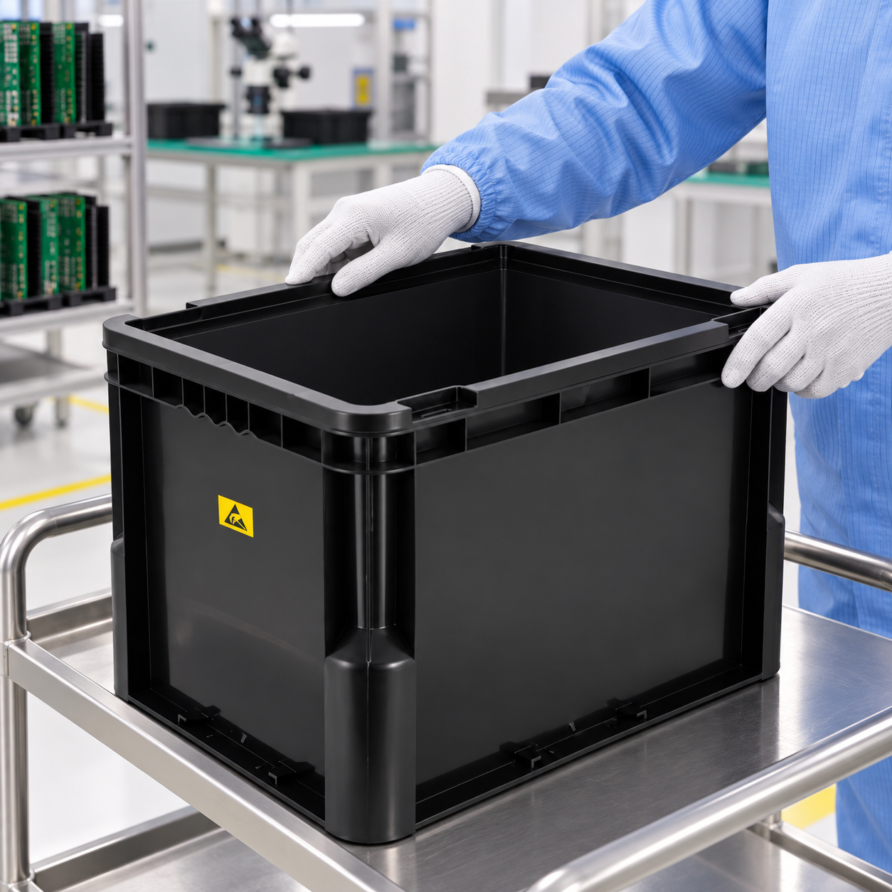
Label the material and container separately
A reusable box asset ID should stay with the box. A temporary material label identifies board revision, lot, quantity, status and destination. If a lid or outer carton is used, do not place the only identity on a part that can be separated from the box. Scan or record at receive, move, split, issue and return. The labeling and MES guide explains the identity layers in a related tray workflow.
Keep held or rework assemblies physically separated from released stock. A box with a readable label but wrong status should not be available to a line-side picker. The ESD warehouse storage guide covers the broader status and location design.
Validate cleaning and reuse
Check the box after a representative use cycle for particles, adhesive, wall damage and warping. Use a cleaning agent qualified for the actual material and any label or liner. Dry and inspect the empty box before assigning a new material lot. A cracked support edge should be quarantined, not hidden under a new pouch.
Keep a replacement rule and asset history. Repeated damage in the same corner may identify a cart or conveyor interface fault. Correct the route rather than simply replacing each failed bin. For maintenance logic, see ESD bin cleaning and contamination control.
Compare three realistic load cases
Test an empty box, a normally loaded box and the worst credible loaded configuration. In the normal case, use the assembly, pouch and separator that production will actually use. In the worst case, include the largest board revision, tallest connector, highest allowed quantity and expected handling tilt. Observe whether the package slides, whether the board bends, and whether the operator can reach the bottom unit without touching its components.
Document the support path. If a pouch rests on a flat base, check that the base does not bow under other packages. If an inner tray supports the board, make sure that tray does not rock or expose a populated underside. A separator should remain in position during the cart route. Do not add foam or dividers to a procurement drawing without qualifying their material, cleanliness and fit.
Repeat the route after a short storage dwell and after a representative cleaning cycle. A box may locate correctly when new but change after handling. Compare samples from the intended production process rather than relying on a single development unit. Keep photographs and sample IDs so quality can reproduce a failure later.
Control rework and returns
A returned PCB assembly may have a different status, exposed contacts or an incomplete protective package. Route it to a defined rework or inspection location, not directly into released stock. Record the work order, board revision, serial or lot identity, reason for return and remaining package condition. If the original pouch cannot be reused, apply an approved replacement before movement outside the EPA.
Keep rework units separate from new assemblies even when they share the same part number. A box can carry a stable asset ID while its contents change, but the material label must be updated for every cycle. This prevents a clean reusable container from giving an old or held assembly the appearance of released stock.
RFQ and first-article checklist
- Released PCB assembly drawing and worst-case envelope.
- Allowed contact and support surfaces.
- Required package and ESD handling route.
- Bin footprint, depth, base support and load.
- Inner tray, liner, separator or lid if specified.
- Cart, conveyor, shelf and shipping trials.
- Asset label, lot label, cleaning and defect criteria.
그 PCB storage and circulation guide gives the end-to-end equipment view. Tray load validation offers complementary thinking for a shallower carrier, but the deep bin must be validated on its own terms.
Further learning: ESD protection context
This EOS/ESD Association lecture gives the electrical background for a PCB assembly handling plan.
자주 묻는 질문
Can a PCB assembly touch the bin wall?
Only at approved support zones under a validated configuration; protect fragile components and contacts.
Does a black ESD box replace a shielding pouch?
Do not assume so. Select packaging from sensitivity, EPA boundary and transport route.
How many boards can share one bin?
Set the quantity from loaded clearance, separation, support and movement tests.
Should the box ID change with every lot?
No. Keep the reusable asset ID stable and link the changing material lot separately.
When should the first article be repeated?
Repeat affected checks after changes to board envelope, package, liner, bin geometry, material or route.
댓글 남기기