- Turbo
- Blog
An esd grounding test failure should trigger a controlled investigation, not an immediate adjustment until the tester displays a pass. Identify the failed measurement, protect affected sensitive work, confirm the measurement system, and isolate the suspected path using an approved procedure. Then correct the verified cause and repeat the original test under documented conditions. A resistance-to-ground result, a wrist-strap check, a metal-bond continuity measurement, and a product immunity test answer different questions. This guide addresses corrective investigation of ESD control grounding paths in electronics production; it does not prescribe electrical installation work or immunity testing.
Establish what failed before replacing equipment
Start with the record that prompted the investigation. Copy the equipment identity, measured value or indication, instrument identity, selected mode, connection points, test method, environmental conditions, and applicable acceptance criterion. Preserve the original result even if an immediate repeat passes. If the operator reports only “ground failed,” ask which item was measured and what the complete path included. A workstation surface measured through its ground cord is different from a direct check of a metallic connection. The expected resistance cannot be selected without that distinction.
Itu EOS/ESD Association grounding overview explains the common-point-ground concept and its relationship to workstation control elements. Use that framework to draw the intended path for the affected station. Compare the drawing with the approved site arrangement rather than assuming every visible metal connection is a valid test point. An equipment-specific shelf grounding and continuity guide provides complementary purchasing context; the investigation here begins after a check has already failed.
Contain affected work and assign responsibility
Follow the site’s response procedure for a failed ESD control item. Move exposed sensitive work only through an approved handling route and protect it using qualified controls. Identify the affected station, rack, or accessory clearly so another operator does not unknowingly resume use. Record when the last documented satisfactory check occurred and what changed afterwards. A failure does not establish that every product handled since that time is damaged, but it does require a responsible quality decision about the potentially affected interval.
Separate the roles of the ESD coordinator, production supervisor, maintenance personnel, and electrical safety authority. The ESD owner should define the measurement and release criteria. Authorized electrical personnel must address protective-earth integrity, mains wiring, and any safety-related defect. Operators should not open electrical outlets, remove protective connections, bypass a designed resistor, or connect improvised wires to building services. A faster production restart is not a sufficient reason to alter the grounding design.
Verify the instrument and its accessories
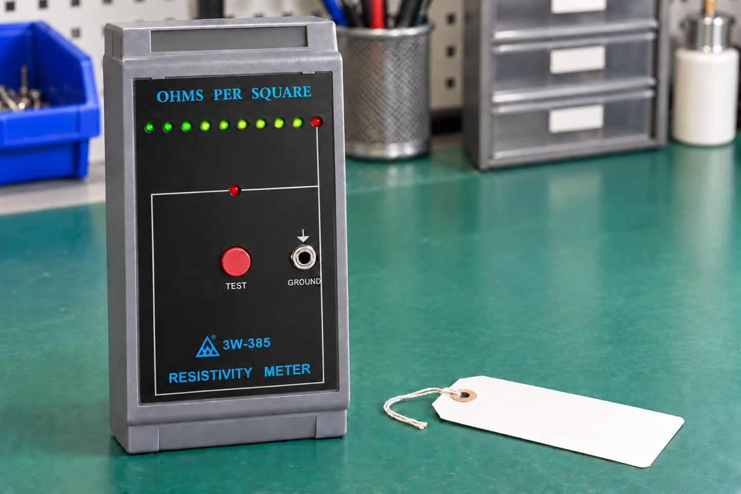
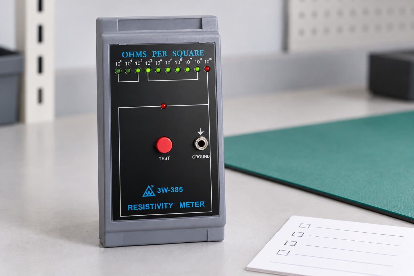
Before diagnosing the installed path, confirm that the instrument is suitable for the specified test. A handheld surface-resistance instrument, a low-resistance continuity instrument, and a personnel tester may have different ranges, test conditions, contacts, and acceptance logic. Consult the exact manufacturer’s instructions and the approved method. The SWESD surface resistance tester illustrates a product category for resistance assessment; its appearance does not establish suitability for every continuity test or certify a station’s electrical safety.
Check identification, calibration status, battery condition where applicable, connector condition, and approved leads. Perform the instrument’s prescribed verification using suitable reference equipment. Inspect leads for cuts, crushed sections, strained ends, and intermittent behavior during permitted handling. A worn connector can create a variable reading that resembles a station defect. Record these checks rather than substituting an undocumented different tester until the indication changes. Where two instruments disagree, reconcile methods and operating conditions before drawing a conclusion.
Trace the path in manageable sections
Create a simple path record from the tested item through its approved contact, cord, common point, and designated ground connection. Mark which portions include resistive materials or intentional components. This prevents a technician from applying the same expectation to a conductive bond and a dissipative surface. Determine which sections can be checked safely without disturbing protective earth or other controlled connections. Only authorized personnel should isolate or disconnect sections where the method and safety procedure permit it.
Use a stepwise investigation. Confirm contact placement first, then examine the accessible accessory or connection that belongs to the failed path. Compare an approved known-good accessory where the procedure allows, keeping the rest of the arrangement unchanged. If the fault follows the accessory, preserve its identity and condition for investigation. If it remains with the station, continue with the next authorized section. Changing the mat, cord, instrument, test point, and operator together may produce a pass while losing the evidence needed to prevent recurrence.
Use the failure pattern to choose the next check
The following decision table suggests investigation directions. It supplies no universal numerical limits. The acceptance criterion and the allowed diagnostic checks must come from the approved method, applicable program requirements, and equipment instructions. In particular, an audible continuity indication is not a substitute for a recorded ESD resistance measurement when that is the required test.
| Observed pattern | Check before concluding | Evidence to retain |
|---|---|---|
| High or open result | Approved contacts, lead condition and allowed path segments | Initial result and isolated segment observations |
| Unexpectedly low result | Correct mode, intended path and intentional components | Method, connection drawing and component identity |
| Result changes with movement | Accessible connector and cord condition under permitted handling | Movement conditions and repeat observations |
| Only one operator fails | Contact placement, timing and procedure understanding | Observed technique and controlled repeat |
| Several stations fail together | Instrument verification, shared change and environmental records | Reference check and change timeline |
| Retest passes without a cause | Intermittent fault and whether conditions changed | Original failure and unresolved investigation status |
An unexpectedly high result may reflect a discontinuity, poor contact, contamination, an unsuitable measurement point, or the behavior of the material being tested. An unexpectedly low result may indicate a different path than intended or a changed component. Neither pattern proves a specific cause by itself. Document the observation and the next discriminating check. An intermittent result deserves particular attention because a satisfactory repeat can hide a mechanical problem that returns during normal movement.
Examine contacts, cleaning, and mechanical changes
Inspect accessible approved contact points for loose hardware, corrosion, damaged finishes, contamination, or a displaced attachment. Verify that the selected point is intended to be part of the measured path. A painted surface may not behave like the conductive substrate below it, but scraping coatings or altering an attachment without authorization can damage equipment or create a different safety problem. Photograph the original condition before any permitted cleaning or repair. Record which surface was treated and which procedure was used.
Review recent changes: equipment relocation, new mats, replaced cords, cleaning chemicals, altered shelves, maintenance activity, and storage rearrangement. Compare the timing of these changes with the first failed result. Cleaning compatibility and the required drying or conditioning period belong in the procedure. A result taken immediately after an uncontrolled treatment may not represent normal operation. For mobile equipment, movement can affect contact conditions; the wire-mesh cart grounding-path guide covers the related equipment-level questions.
Keep environmental and material effects separate
Record temperature and humidity when the method requires them, and compare conditions with qualification and verification records. Do not add humidity or use an unapproved spray simply to make a failing reading lower. A conductive connection fault and the resistance behavior of a dissipative material require different investigations. The measurement location, contact arrangement, stabilization time, and environmental condition can all affect the interpretation of a material test. Keep those factors visible in the report rather than reducing the result to a single green indicator.
Itu EOS/ESD Association control-principles overview distinguishes grounding of conductive or dissipative items from the treatment of insulating materials. That distinction matters during troubleshooting: attaching a wire to an ordinary insulating object does not establish the desired charge-control behavior. If a grounded station still has a process charging problem, involve the ESD owner in a broader assessment rather than declaring the grounding check sufficient for every hazard.
Correct the verified cause and repeat the original check
The corrective action should match the evidence. Replace a confirmed damaged accessory with an approved equivalent, restore an authorized connection, or correct a documented measurement error through training and procedure revision. Record the replacement’s identity and the approval basis. If the original design is unsuitable for the application, treat the solution as an engineering change with qualification and updated documentation. Do not disguise a design change as routine maintenance.
After correction, repeat the original required measurement at the specified points with the specified conditions. Add relevant verification checks where the repair could affect adjacent controls. Retain both the failed and satisfactory records, the identified cause, the action taken, and the release decision. A pass obtained with a different method cannot close the original failure without explanation. If no cause was found, record an unresolved intermittent condition and apply the site’s escalation rule instead of inventing a diagnosis.
Build a useful corrective-action record
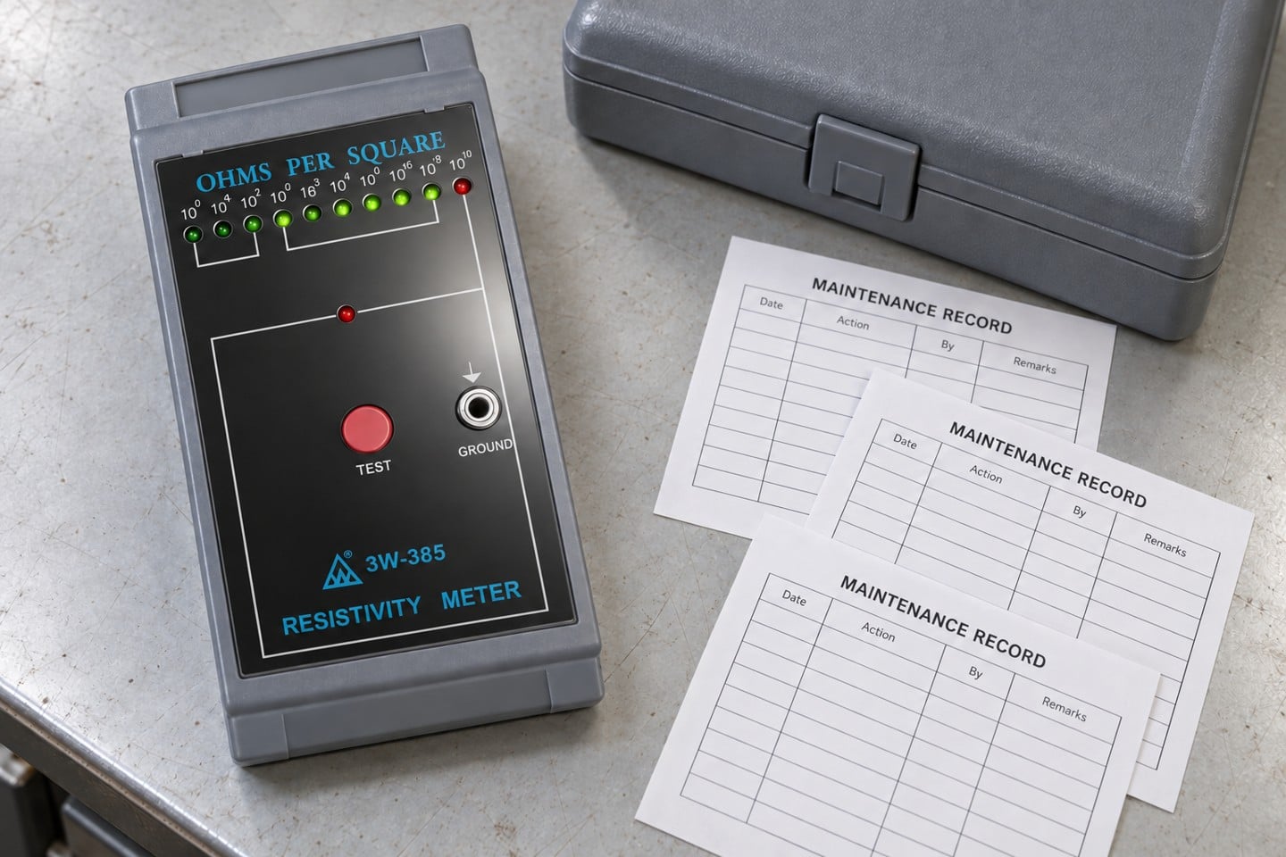
A concise record should let another qualified person reproduce the reasoning. Include the item and location, method revision, acceptance basis, instrument and accessory identities, initial result, conditions, investigation sequence, photographs, confirmed cause, correction, retest results, and release authority. Add the affected-work disposition separately so the station repair and product-quality decision remain traceable. The ESD test report template helps organize the measurement evidence without turning this troubleshooting guide into another generic testing checklist.
Track repeat incidents by failure mode rather than only by station number. Several failures following a cleaning change suggest a different prevention action from repeated damage at a connector. Set follow-up frequency through the program’s risk assessment and documented verification plan. This article does not assign a universal daily, weekly, or annual interval. A reliable prevention action addresses the mechanism found in the investigation and includes evidence that it remains effective under actual production use.
Educational background for the investigation
The following EOS/ESD Association educational video provides background on ESD control. It supports understanding of the broader protection program and does not authorize electrical repairs, define instrument-specific settings, or replace the controlled test procedure. Use the written investigation steps and your approved documents to make the release decision.
Pertanyaan yang sering diajukan
Does a failed grounding check prove product damage?
No. It establishes a control issue requiring containment and a responsible assessment of affected work; product disposition needs its own evidence.
Can a surface resistance tester verify every grounding path?
No. Confirm that the exact instrument and accessories support the approved method and required measurement range.
Should an intentional resistor be bypassed to obtain a pass?
No. Do not alter designed components or protective connections to change an indication. Escalate the issue to the responsible authority.
Can an immediate satisfactory repeat close an intermittent failure?
Not by itself. Preserve the first result, compare conditions and investigate the suspected intermittent cause before release.
Which result should be used after correction?
Repeat the original approved test under documented conditions and retain the failed result, corrective action, retest and release decision.


Tinggalkan Balasan