- Turbo
- Blog
ESD resistance test probes and concentric ring electrodes answer different measurement questions. Two contacts can examine a defined point-to-point path or a small accessible surface, while a qualified concentric arrangement can support a surface measurement whose geometry is specified by the method. They are not interchangeable simply because both connect to a resistance meter. Choose the required measurement first, then confirm electrode geometry, contact conditions, instrument compatibility and the acceptance rule. A favorable reading from an improvised contact arrangement does not prove that a material meets a specification written for another method. Keep raw resistance, any calculated quantity and the actual test setup distinct.
Start with the quantity in the specification
Before requesting an electrode quotation, identify whether the requirement concerns point-to-point resistance, resistance to ground, surface resistivity or another property. These quantities can involve different paths and different arrangements. A material specification may call for a standardized specimen measurement, while a production check may examine an installed assembly. Write the required quantity and applicable method in the request. If the requirement only says ESD resistance, ask the technical owner to clarify it before comparing supplier results. Otherwise, different laboratories can produce plausible numbers that answer different questions.
El ESD Association’s basic control procedures and materials guidance provides the broader context for selecting and evaluating control materials. It does not mean that one unspecified electrode arrangement proves every property of a finished package. Keep the property claim within the measurement scope. For example, a surface reading alone does not establish that an open container provides discharge shielding during transport. Match the evidence to the function the buyer actually needs rather than treating the word conductive as complete approval.
What two-point contacts can tell you
A pair of contacts establishes a path through or along the specimen under the stated arrangement. Contact size, spacing, pressure and surface condition affect what is being measured. Small contacts can be useful when the available surface is narrow, curved or interrupted, but the method must address those limitations. Record where the contacts sit and whether the measurement follows the intended surface path. A rib, joint or opening between contacts may make the result different from a measurement on a continuous flat sample, even when both results are displayed in ohms.
Two-point probing should not be described as a universal surface-resistivity method. Where a qualified method allows a conversion, retain its geometry and calculation alongside the raw reading. Where it does not, report the defined resistance measurement without relabeling the units. The surface resistance versus resistivity comparison explains why changing a label cannot normalize an arbitrary contact arrangement. For procurement, ask the supplier to identify the procedure and give enough setup information to reproduce the result rather than requesting a single unexplained value.
What a concentric arrangement adds
A concentric electrode arrangement provides a defined relationship between an inner contact and an outer contact around it. In a suitable method, this geometry can support evaluation of a surface quantity while helping define the measurement path. The exact electrode design, specimen requirements and conversion belong to the applicable procedure. Do not infer the correct factor from an illustration or copy dimensions from a different electrode model. Ask for the method reference and the actual geometry of the electrode supplied with the test system.
The specimen must accommodate the arrangement. A small tray pocket or heavily ribbed surface may not provide the flat, continuous area that the procedure requires. Pressing a ring across ribs does not automatically create valid contact everywhere. Likewise, a coating that has worn differently at the contact locations can change the measurement. Document these conditions, and obtain an approved alternative method or suitable representative specimen where necessary. Do not grind away features or flatten a molded product unless the sampling procedure specifically permits that preparation and its implications are understood.
Compare contact conditions as carefully as geometry
Electrode contact material, cleanliness, loading and placement influence repeatability. Request the specified contact preparation and any restrictions on cleaning. Residue from a cleaner can alter a surface or the electrode itself, so an apparently cleaner contact is not necessarily a better controlled contact. Keep the contact condition consistent between specimens and record relevant changes. A test report should identify the arrangement and any preparation that materially affects the result, not just name the meter and show a photograph of its display.
For weighted electrodes, use the mass and contact conditions required by the approved method. Do not add pressure by hand to stabilize a reading unless that action is prescribed and controlled. For small probes, identify how contact force and position are controlled. Different operators can otherwise produce different results from the same sample. Where a contact repeatedly slips or bridges an unintended feature, stop and review suitability. A quick reading that is difficult to reproduce creates a weak basis for accepting a supplier lot.
A practical selection table
| Question | Two-point arrangement | Concentric arrangement |
|---|---|---|
| Required quantity | Defined path between contacts | Defined inner-to-outer geometry under the selected method |
| Available surface | May access a limited area where a qualified method permits | Needs a suitable area for the complete contact arrangement |
| Result description | Record resistance and placement | Record raw reading and applicable geometry conversion |
| Repeatability control | Contact position, force and condition | Contact completeness, loading and specimen condition |
| Approval evidence | Qualified procedure and exact accessory compatibility | Qualified procedure, geometry and exact system compatibility |
This table is a decision guide, not a substitute for a specified test method. It deliberately avoids universal dimensions, masses and resistance limits because those values must come from the applicable procedure and actual equipment. Use it to identify missing information in an RFQ and to decide which questions need a laboratory or ESD program owner’s answer. If a supplier offers both probe and ring options, request separate evidence of what each arrangement can measure and the specimen limitations that apply.
Confirm the instrument and accessory combination
Check the meter’s measurement function, range, test settings, connector arrangement and compatibility with the proposed accessory. A matching-looking plug does not prove compatibility. Obtain documentation identifying the instrument and electrode combination, including any required cable arrangement and restrictions. A handheld tester with built-in contacts may support a different measurement from a laboratory system with external electrodes. Do not assume that an accessory is supplied or supported simply because a product category page discusses surface resistance.
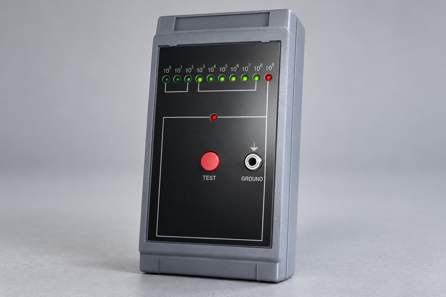
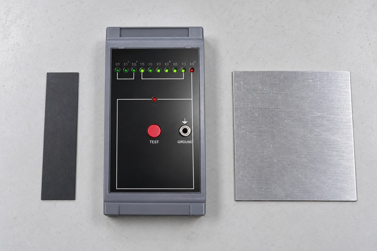
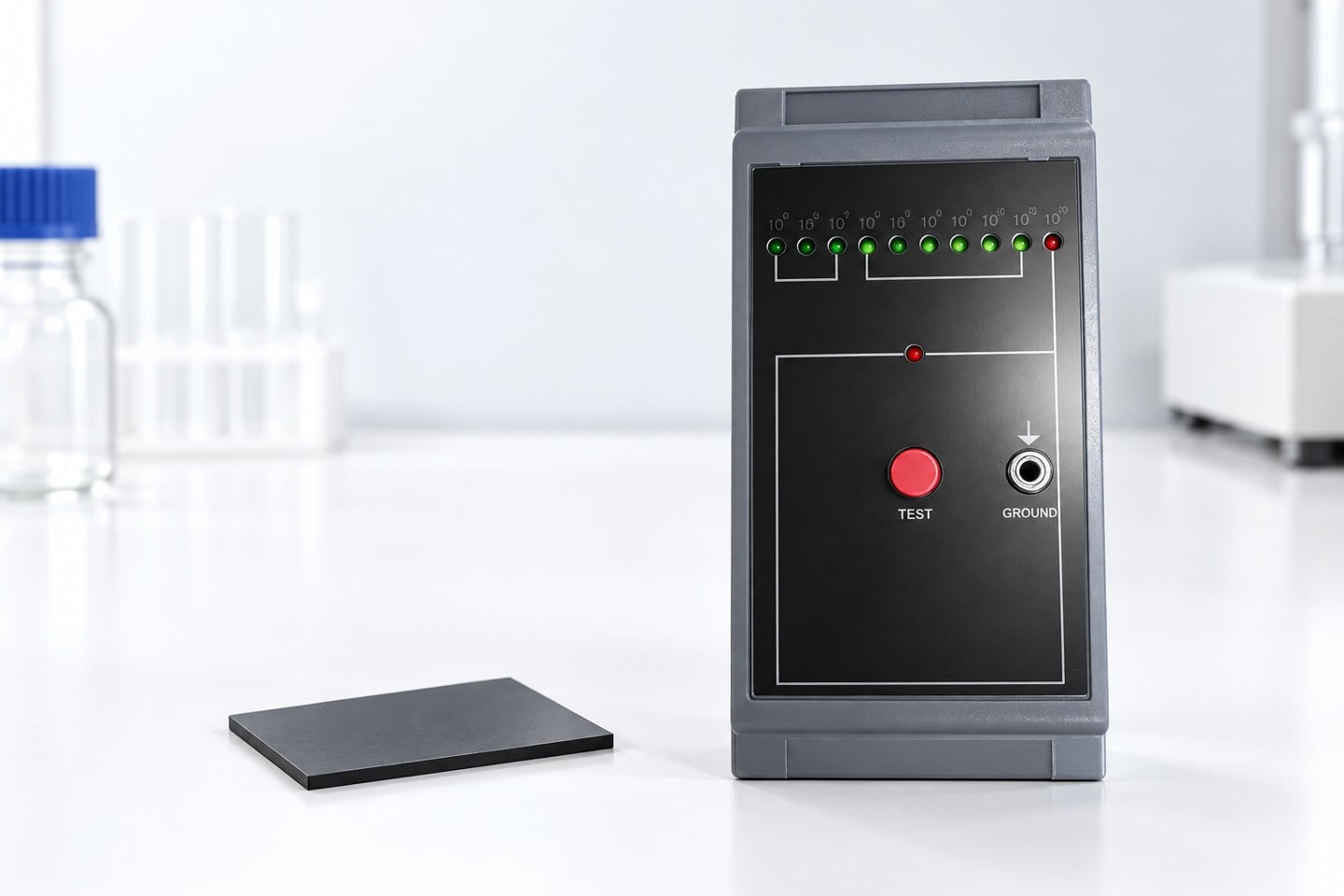
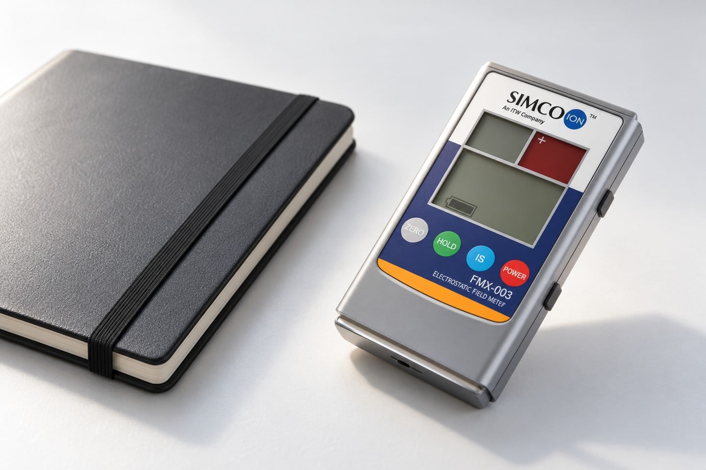
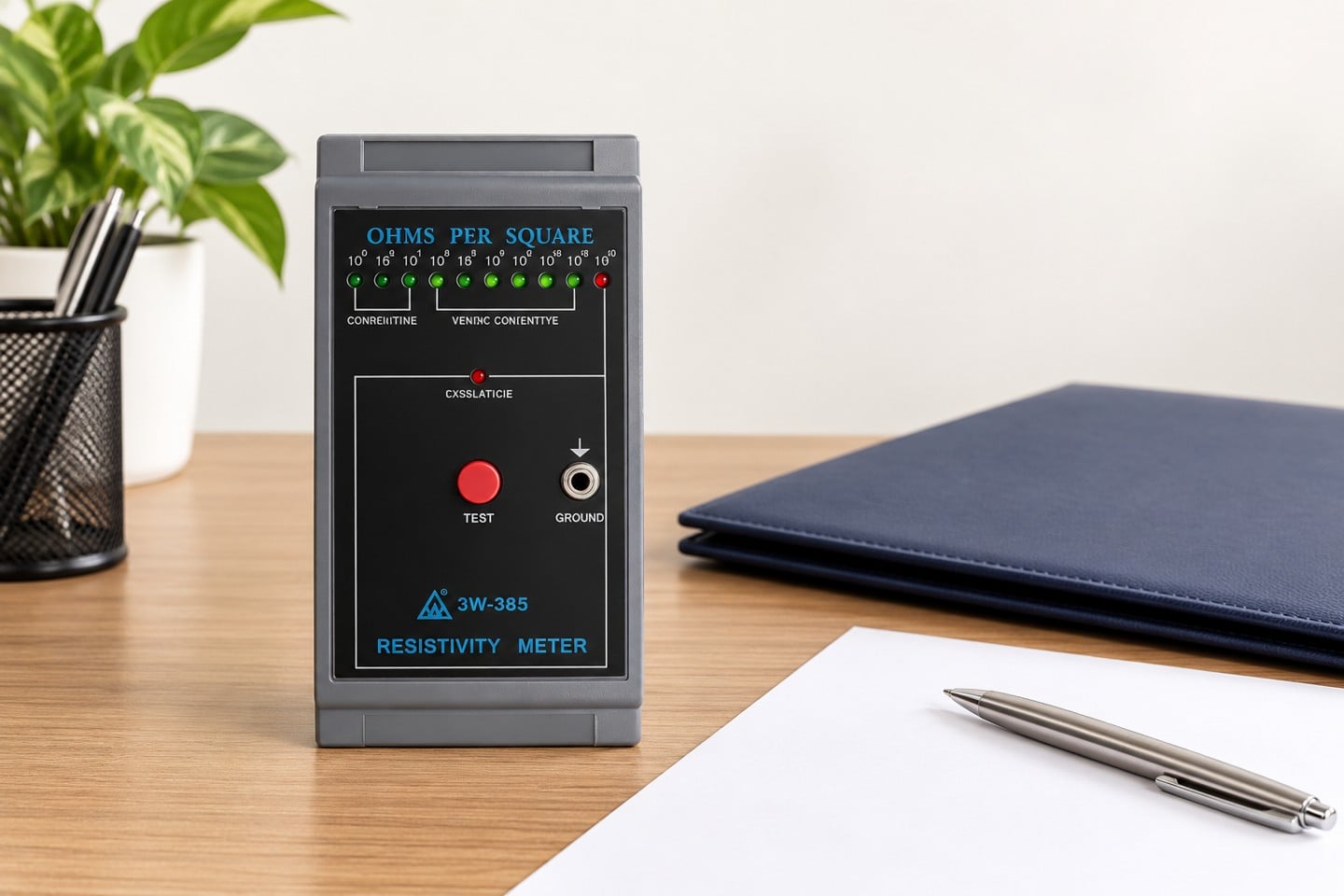
El SWESD handheld surface resistance tester is shown here only as the real product reference for the illustrations. The images do not establish compatibility with external probes or a concentric electrode. Request confirmation for the actual supplied model before ordering accessories. The existing surface resistance tester guide provides operating context, while the surface resistivity test-method discussion helps keep the property and procedure aligned. Neither replaces the documentation for a specific electrode system.
Control specimen conditioning and environment
Record specimen identity, preparation and environmental conditions required by the method. Conditioning can be important when comparing materials or evaluating performance under different humidity conditions. Distinguish the humidity during conditioning from the humidity at the time of measurement. If a sample is moved between environments, record the transfer and any stabilization time specified by the procedure. Do not describe a single room reading as proof of how a material will behave in every production or transport condition.
Keep the same conditioning and measurement arrangement when comparing electrode options. If geometry, contact loading and humidity all change at once, an observed difference cannot be assigned confidently to the electrode alone. Plan a controlled comparison with the responsible technical owner. Identify which factor is being varied and which factors remain fixed. This makes a useful investigation possible without pretending that a few uncontrolled readings establish equivalence between two methods. Record individual results and anomalies so later reviewers can see the limits of the comparison.
Interpret differences without forcing agreement
Two arrangements may produce different readings because they examine different paths or normalize geometry differently. That does not automatically mean one instrument is defective. Review quantity, placement, specimen condition, contact and settings before comparing values. If both results are valid within their own scope, report them separately. Do not average them into a single product property or choose whichever result satisfies the commercial specification. The acceptance decision must use the evidence required by the agreed method, with deviations identified clearly.
NIST’s discussion of metrological traceability explains why a supported measurement result requires more than an instrument label. Calibration evidence for the meter should be relevant to the measurement, but it cannot compensate for an unsuitable electrode arrangement or undocumented specimen preparation. Retain the calibration scope and any relevant uncertainty information alongside the method and actual observations. When a result is close to an acceptance boundary, use the agreed decision rule rather than assuming that the displayed final digit settles the question.
Specify an RFQ that can be evaluated
Give the supplier the specimen description, available contact area, required quantity, applicable method and intended operating conditions. Ask for electrode drawings or documented dimensions, contact materials, specified loading, cable requirements and compatibility evidence for the exact meter model. State which items must be included and which are optional. Request a sample report showing individual results, test settings, conditioning, placement and deviations. This is more useful than asking for an ESD probe set with no description of the measurement it must support.
Before accepting the system, have the responsible users perform an approved demonstration on representative specimens. Verify that positioning is practical, results are recorded correctly and the procedure can be repeated without improvised pressure or altered contacts. Establish cleaning, storage, inspection and replacement controls for the accessories. Keep the tester calibration guide available for the instrument evidence, while maintaining a separate accessory record. A well-specified measurement system joins instrument, electrode, specimen and method into one documented arrangement; buying a meter alone does not complete that work.
Educational background
The following educational video introduces electrostatic behavior. It supports understanding the reason for controlling ESD-related materials, but it is not an electrode selection procedure and does not define the dimensions, contact pressure or acceptance limits for your test. Use the applicable method and qualified equipment documentation for those details.
Preguntas frecuentes
Are two probes interchangeable with a concentric electrode?
No. Confirm that the quantity, geometry and specimen requirements match the applicable method before using either arrangement.
Can a point-to-point reading be called surface resistivity?
Only when the applicable method supports a documented conversion. Otherwise retain the resistance value and the actual contact arrangement.
Can a ring electrode bridge tray ribs?
Do not assume it provides the contact required by the method. Review specimen suitability and obtain an approved alternative where needed.
Does a matching connector prove compatibility?
No. Obtain documentation for the exact meter and accessory combination, including functions, settings and cable requirements.
Why do the arrangements give different readings?
They may examine different paths or contact conditions. Review the method and conditions before interpreting the difference as a material or instrument failure.
Dejar un comentario