- Turbo
- Blog
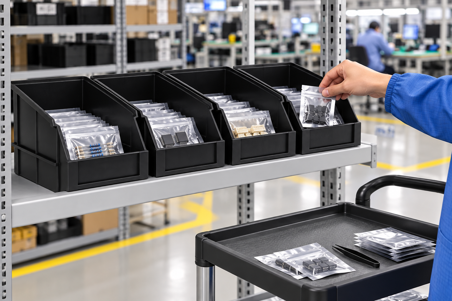
ESD trays for automated material handling must work as both protective packaging and a repeatable machine interface. A tray that protects a component on a bench can jam at a guide rail, arrive in the wrong orientation, or shift under a robot gripper. Specify the outside envelope, base support, rim, loaded center of mass, identification zone, and ESD behavior together. Then validate the loaded tray on the actual conveyor, lift, camera, gripper, and storage route. The goal is a predictable handoff from each machine to the next without hidden contact or identification errors.
Map the entire material route before choosing a tray
Draw the movement sequence from loading to unloading: operator or machine load, transfer conveyor, buffer, vertical lift, automated storage, retrieval, line-side delivery, and return. Note every change of orientation and every place the tray is lifted or stopped. The same tray may be supported on rollers in one zone and only by its two side rails in another. A stable assembly at one station is not evidence for the entire route.
NIST describes manufacturing automation applications including mobile material handling, machine tending, and machine vision in its robotics and manufacturing automation overview. For tray selection, use that systems view: the interface between devices matters as much as the device itself.
Define the outside envelope and support surfaces
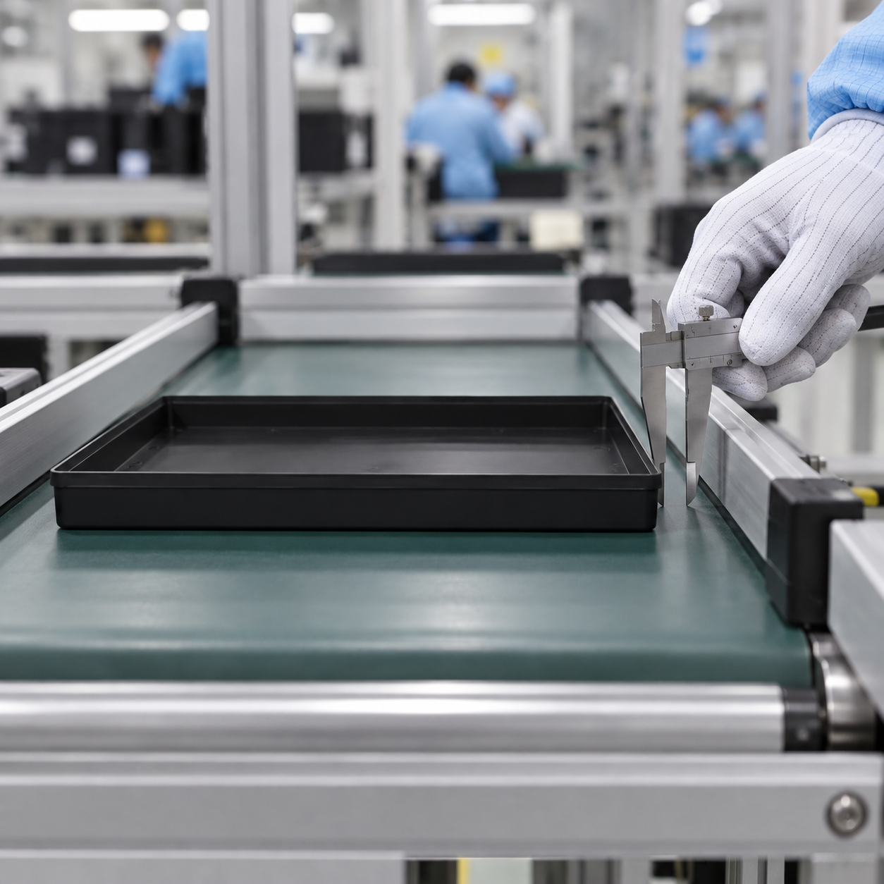
Record tray length, width, height, wall draft, corner radius, bottom flatness, and the height of any label holder or liner. Measure samples from the intended process, not only nominal CAD dimensions. Identify the surfaces the equipment is allowed to touch. A conveyor guide must contact a robust outer wall or designed rail, not a thin edge that can bend into the product cavity.
Include the minimum and maximum loaded condition. A heavy asymmetric load can move the center of mass and increase rocking at a transfer gap. A component projecting above the rim may be safe on an open conveyor but unsafe under a fixed camera or inside a storage cell. Build a clearance model for the full loaded assembly.
| Interface | Tray feature to specify | Validation method | Failure to watch |
|---|---|---|---|
| Roller or belt conveyor | Flat support footprint and stable base | Loaded start, stop, and transfer trial | Rocking or bridging a gap |
| Guide rail | Outer wall and clearance | Worst case width and skew trial | Binding or wall deflection |
| Robot pickup | Repeatable grip or lift zone | Cycle test across sample variation | Slip or product contact |
| Camera or scanner | Orientation and label zone | Read trial under production lighting | Hidden or unreadable identity |
| Storage cell | Stack pitch and loaded height | Insertion and retrieval trial | Rim or part collision |
These are project checks. Set numerical acceptance criteria from the equipment and component drawings rather than copying values from another facility.
Prevent orientation errors
Choose one loading orientation and make it observable. An asymmetrical part cavity or removable label may tempt operators to rotate a tray, but the automation could then read the wrong corner or grip the wrong side. If the tray is intentionally reversible, prove that every interface works in both orientations. Otherwise, use a controlled marker, locator, or scan check so the line stops before a wrong orientation reaches a robot.
Document how empty trays return. Some designs nest differently from their loaded stacking orientation. The stacking and nesting guide covers this boundary. A system that assumes every tray has the same pitch must detect empty-return mode before storage.
Validate robot pickup and placement
Define whether the robot handles the tray, the component, or both. For tray pickup, identify a grasp zone that stays clear of labels, liners, and delicate parts. Test the lightest and heaviest approved load, maximum permitted offset, and samples from different production lots. Check acceleration, deceleration, emergency stop, and recovery after a missed pickup. A tray that survives slow teaching motion may fail at production speed.
For component placement, check cavity or support repeatability. A machine vision system may correct part position, but it cannot compensate for an unstable tray or an occluded feature. Use an inspection station that confirms the tray ID, orientation, and empty or occupied state before motion begins. Keep manual recovery steps in the work instruction so operators do not improvise around a jam.
Design identification for the equipment
Place barcodes or RFID tags where the reader can access them during the actual movement. Avoid the rim, base support, grip surfaces, and areas that scrape a neighboring tray. Specify the permanent tray asset ID separately from the temporary part, lot, and work order data. GS1 US explains one industrial barcode option in its GS1-128 overview. The related ESD tray labeling and MES guide describes transaction and reprint controls.
Run the scan at the worst practical angle, speed, and lighting. Test a dirty label, partially filled tray, and a tray at the edge of its dimensional tolerance. Define what the system does on no-read, double-read, and duplicate ID. Do not let the automation silently assign a guessed identity.
Keep ESD performance separate from mechanical fit
A mechanically compatible tray is not automatically suitable for an ESD-sensitive device. Specify the packaging property and the environment in which it applies. The EOS/ESD Association’s ESD fundamentals explain the role of packaging in a control program. Ask for the applicable material test record, and verify that cleaning, labels, and wear do not undermine the approved handling method.
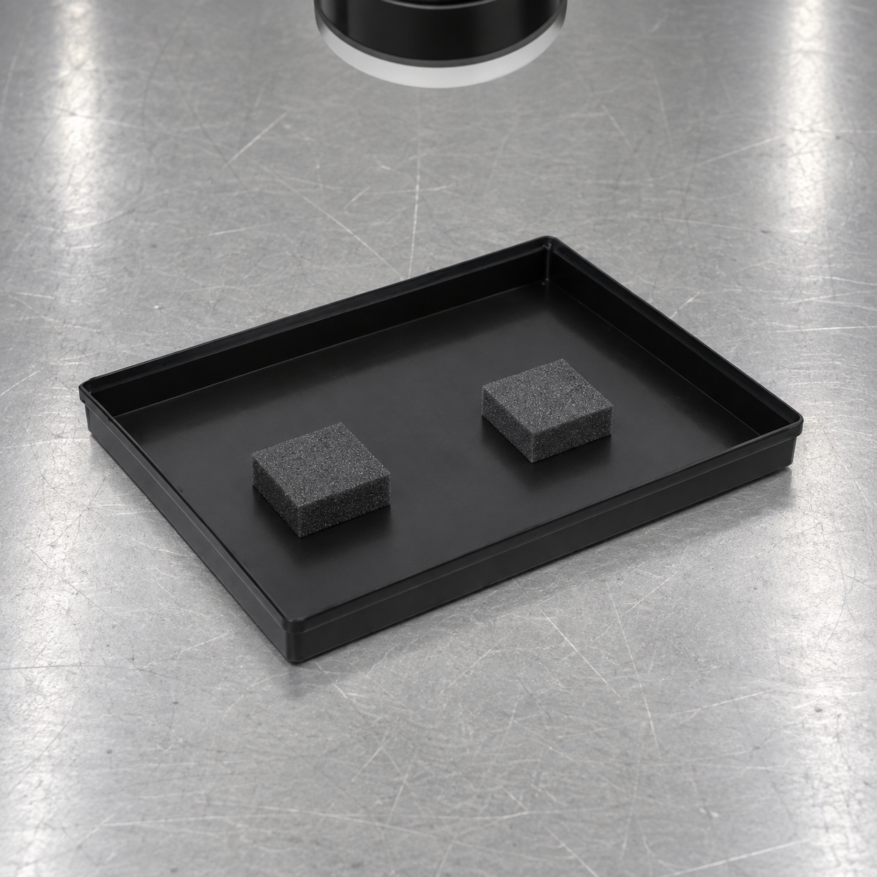
For contact-sensitive parts, also control debris, sharp edges, and friction. A gripper may repeatedly rub one wall and create damage even when the tray passes a one-time fit check. Inspect trays after a representative number of cycles and set a replacement rule based on actual wear evidence.
Run a realistic acceptance trial
Use production-intent trays and the actual component or a formally approved surrogate. Capture cycle time, jams, no-reads, mispicks, spills, and visible wear. The trial should include startup, normal speed, stop and restart, partial loads, the heaviest load, and an empty return. Record the number of cycles and the exact equipment settings so a later design revision can be compared on the same basis.
NIST’s material handling system architecture report illustrates how tray roller tables, storage and retrieval, guided vehicles, and controllers interact. A modern site may use different equipment, but the lesson for acceptance remains useful: validate the handoffs and information flow as one system.
Diagnose failures at the handoff where they occur
When a tray jams, record the station, travel direction, loaded mass, tray ID, temperature, and the exact point of contact. Compare the failed unit with a released sample before changing the equipment. A width problem may be caused by tray variation, a loose guide, a protruding label holder, or a load that bows the wall. Each cause needs a different correction. Avoid widening every guide until a separate station loses the ability to locate the tray.
A no-read should trigger an inspection of the symbol, its location, lighting, camera angle, and software record. A robot miss may originate in tray placement, gripper wear, vision calibration, or an unexpected part height. Record both the mechanical and information state at the failure. This lets the engineering team revise the responsible interface and rerun a bounded trial.
After correction, verify the affected step and the downstream route. Moving a label to help a scanner can obstruct stacking; changing a rim to help a gripper can affect storage pitch. Update the controlled drawing, machine recipe, and operator instruction together so the next production lot does not repeat the same fault.
What to include in an RFQ
- Tray drawing, revision, material and required electrical behavior.
- Component envelope, mass, support and prohibited contact areas.
- Conveyor, guide, lift, gripper, camera and storage drawings.
- Minimum and maximum loaded configurations.
- Label zone, code format and scan direction.
- Cleaning, cycle life, inspection and replacement requirements.
- Acceptance trial cases, sample quantity, and failure disposition.
Benutzen Sie SWESD ESD tray family as the product reference and provide the equipment route for a custom review. The component tray guide covers the wider selection context. For early design samples, see CAD to first article prototyping; for loaded support, see tray load capacity.
Further learning: ESD material handling context

This EOS/ESD Association lecture explains the electrical protection context; the machine interface checks above remain project specific.
Häufig gestellte Fragen
Can an ordinary ESD tray run on a conveyor?
Only after its base support, outer wall, loaded stability, clearance and ESD behavior have been validated on the actual route.
What should a robot grip?
A documented tray handling zone that does not contact parts, labels or thin unsupported walls, verified across realistic loads and sample variation.
Is machine vision enough to identify a tray?
Vision can help confirm orientation and load state. A controlled ID and transaction record are still needed for traceability.
How should empty trays return?
Define their orientation, nesting or stacking mode, identity and route separately from loaded material flow.
When should the automation trial be repeated?
Repeat affected tests after changes to tray geometry, material, label, liner, load, equipment, speed or handling logic.
Schreiben Sie eine Antwort