- Turbo
- Blog
A custom ESD tray prototype should prove that the released design can hold, protect, identify, and move the actual electronic part through its intended route. Begin with a controlled CAD definition and part envelope. Then build a representative sample, inspect its critical features against the drawing, test the loaded tray in the real process, and approve a first article from the intended production method. A good looking sample alone does not establish dimensional repeatability or ESD suitability. This guide follows the engineering path from CAD to a recorded release decision.
Freeze the use case before drawing the tray
Collect the part model, drawing revision, mass, delicate surfaces, allowable contact areas, and orientation. Map every handoff: loading, inspection, storage, transport, automated pickup, and unloading. Note the equipment envelope, shelf pitch, cart restraint, conveyor guide, and any robot gripper. A tray optimized for an operator’s bench can fail when it enters a narrow conveyor or is stacked with a label on its rim.
Identify the environment as well. An EPA, cleanroom, dry cabinet, or shipping route can require different controls. The EOS/ESD Association explains packaging choices in its ESD fundamentals; the ANSI/ESD S541 packaging standard listing identifies the current packaging document. Specify the requirement and verification method rather than assuming a black material is suitable.
Build a controlled CAD and drawing package
The CAD model communicates geometry, but a prototype request also needs a revisioned drawing or equivalent product definition. Identify datums and tolerances for the features that matter to fit: outside footprint, pocket size, support lands, rim location, stack pitch, and clearance above the component. State where a part may touch the tray and where it must remain free. Mark label and handling zones so an accessory cannot later intrude into the load path.
Include the material grade or performance specification, finish, cleaning method, and traceability requirement. If several manufacturing routes are possible, name which one the first article must represent. Thermoforming and injection molding can produce different wall profiles, draft, tool marks, and repeatability. A model without process assumptions may invite an attractive sample that cannot be reproduced economically.
| Design input | CAD or drawing decision | First article evidence |
|---|---|---|
| Part contact | Approved support points and prohibited surfaces | Loaded fit photographs and contact inspection |
| Equipment fit | Outside footprint and datum scheme | Measured dimensions and line trial |
| Stacking | Rim, base, pitch, and orientation | Loaded stack and clearance check |
| Ochrona przed ESD | Material and applicable test method | Supplier records and agreed test result |
| Identyfikacja | Label zone outside contact features | Scan and interference test |
The table is a project checklist, not a numerical standard. Acceptance limits must come from the approved product definition and process requirements.
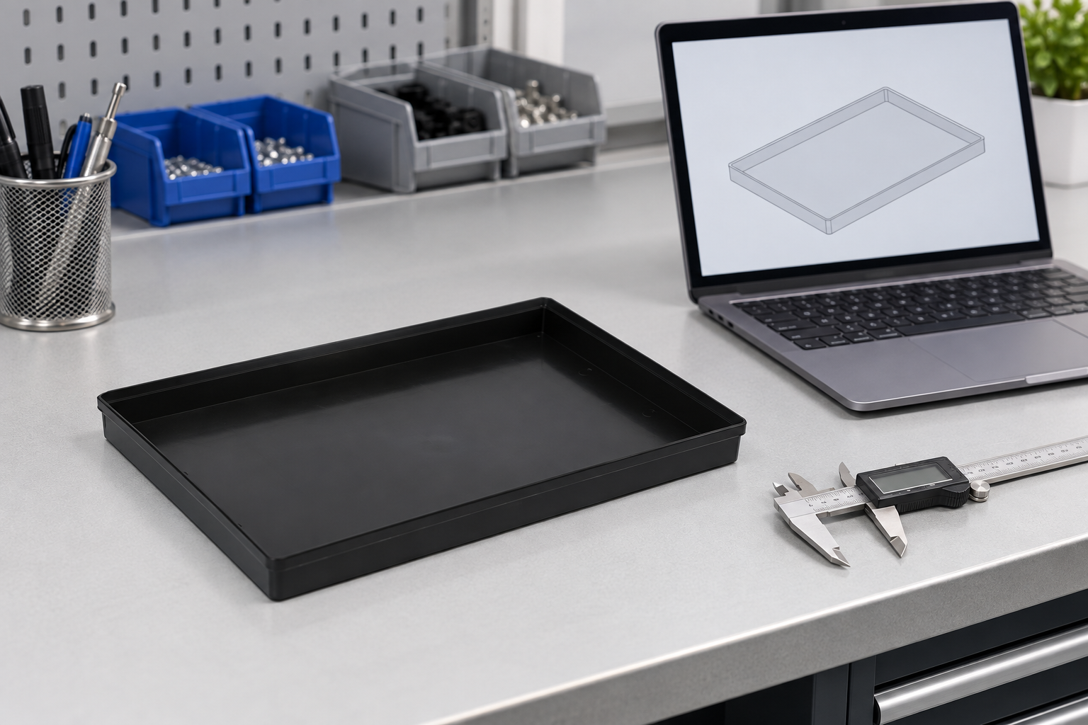
Choose a prototype that answers the right question
An early mockup can check footprint and operator access. It does not necessarily prove material performance, tool repeatability, or production surface finish. State what each sample is intended to validate. A rapid sample may answer whether a part fits; a production intent sample should answer whether the intended material, tool, and process produce a conforming tray.
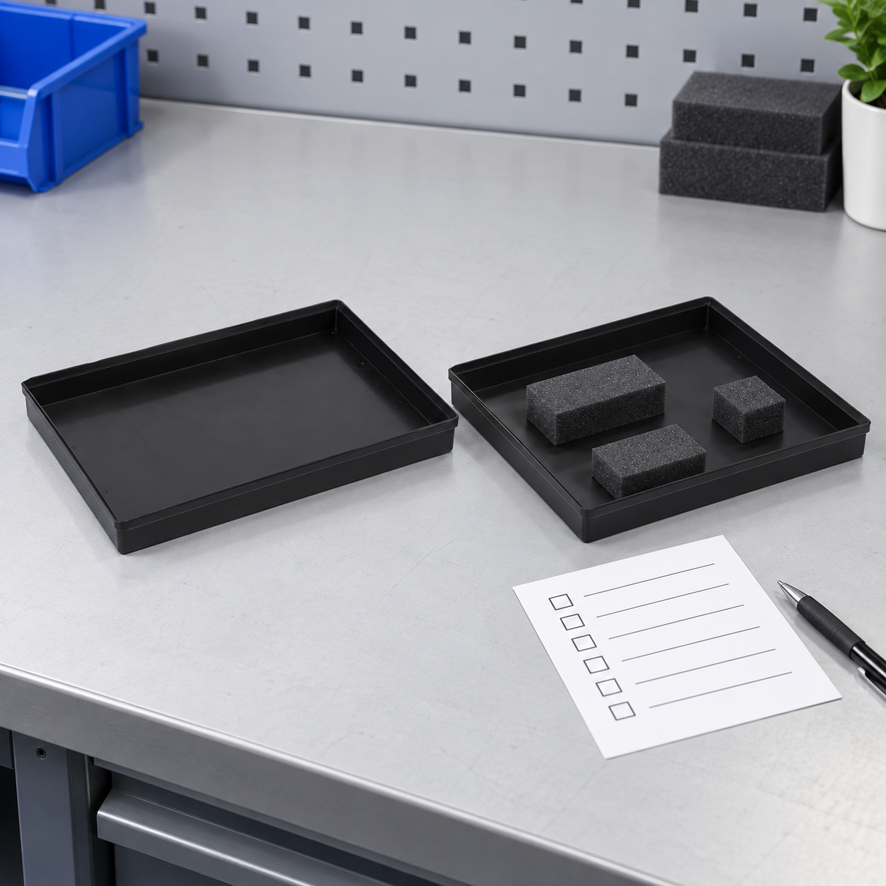
Ask for more than one sample when variation matters. Compare corners and long walls across units. A single hand selected prototype can hide a tooling or setup issue. If the final product uses a liner, label holder, cover, or separator, include those in the trial; accessories can change fit, cleanliness, and stack behavior.
Inspect critical dimensions against the design
Use a measurement plan tied to drawing features, not an unstructured list of numbers. Measure the exterior interface, part supports, cavity clearance, rim geometry, and flatness where those features control performance. Record the instrument and method. A flexible polymer tray can move under the force of a caliper, so an inspection fixture or optical method may be more suitable for some features. NIST discusses selecting measurement equipment in its inspection planning research.
Compare measured values with the released revision. For each deviation, record whether the part still fits and whether the process owner accepts a drawing change. Do not silently change the acceptance limit to match the prototype. Keep the sample ID, tool or cavity, material lot, and inspection date with the record.
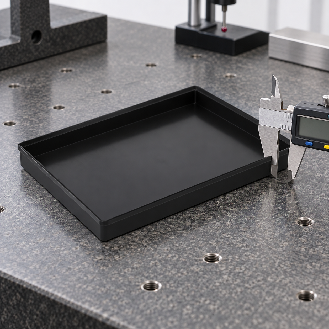
Test the actual loaded handling route
Load the real component or an approved dimensional surrogate in the intended orientation. Confirm that support points avoid fragile surfaces and that the part cannot rotate into a harmful contact. Run the tray through representative loading, picking, shelving, carts, conveyor guides, and unloading. Include ordinary operator variation such as a slightly off center placement. Observe any rocking, snagging, bowing, or part contact.
For stacking, test the loaded assembly, not only two empty trays. A short bench stack may not reveal long dwell deflection or movement on a cart. The related ESD tray load capacity guide describes how support span and load distribution change the result, while the stacking and nesting guide covers the interface between trays.
Verify material, surface, and cleanliness separately
Mechanical fit cannot establish ESD protection. Ask for the material declaration, the electrical property required for the use case, and the test method. Check whether the result applies after cleaning or repeated handling. If the tray is used near sensitive devices, agree on the relevant contamination and particle requirements with the process owner. Keep measurement traceability documented, while ESD requirements should follow the applicable packaging and customer documents.
Inspect burrs, sharp edges, loose particles, and residues. A sample may meet its dimensions yet fail because a molded edge scratches a package or a cleaning method leaves a film. Record the defect location and the corrective action before another sample is made.
Approve the first article from the intended process
First article approval should be linked to the released design revision and production method. The approval packet can include the drawing, measured characteristics, material records, photographs, loaded fit results, process trial, ESD evidence, and any accepted deviations. NIST’s model based enterprise report discusses connecting CAD definition and inspection information; the practical point is that design and quality teams need the same controlled characteristics.
Do not approve production because a prototype “looks good.” Assign each open issue an owner and disposition. If the design changes, revise the model and repeat affected checks. If the tool, resin, process, or supplier changes after approval, determine which tests must be repeated before release.
Use an explicit release meeting with design, quality, manufacturing, and the receiving team. Walk through every critical characteristic and its evidence. Record any concession with its expiration and affected quantity, rather than allowing it to become an undocumented new tolerance. Keep rejected samples for comparison when a later revision is tested. A clear decision record also helps incoming inspection recognize which features must be checked on production lots and which were only development questions.
After a pilot lot, compare its measurements and fit results with the first article. A first article from one setup cannot by itself show that the process will remain stable. Use the pilot to confirm the inspection method, packaging, labels, and handling instructions before increasing volume.
Give the supplier a complete RFQ package
Send the CAD model and controlled drawing, part sample or envelope, expected annual quantity, batch sizes, material requirements, planned cleaning, labeling method, and required first article evidence. Define sample quantities, approval milestones, and what happens if a characteristic fails. Ask the supplier to identify tooling assumptions and any features that are difficult to hold. This conversation is most useful before a tool is committed.
For a broader purchasing checklist, see custom IC tray RFQ and prototype approval. That page focuses on the buying package; this article focuses on the engineering progression from CAD definition through first article measurement.
How this relates to SWESD products
The SWESD ESD tray product page shows the relevant tray family. Use it to discuss the physical form, then provide the actual component drawing and handling route for a custom review. The component tray guide gives broader context, and material selection should be resolved alongside geometry. None of these pages substitutes for validating the final sample against the user’s requirements.
Further learning: ESD material context
This EOS/ESD Association lecture gives the electrical protection background that should accompany a mechanical prototype review.
Często zadawane pytania
Is a CAD model enough to order a custom ESD tray?
No. Provide a controlled product definition, part and process envelope, material requirements, inspection criteria, and sample approval plan.
Can a rapid prototype be the first article?
Only if it represents the intended production material, tool, and process for the characteristics being approved. Otherwise it is a development sample.
Which dimensions deserve priority?
Prioritize the part support, exterior equipment interface, rim and stack geometry, and clearance to fragile features. The drawing sets the actual limits.
Does black plastic prove ESD suitability?
No. Verify the specified electrical behavior using an applicable method and agreed acceptance criteria.
When should first article checks be repeated?
Repeat affected checks after changes to the design, tool, material, process, supplier, liner, label, or handling route.

Napisz odpowiedź