- ターボ
- ブログ
ESD tray load capacity is not a single safe number for every tray that shares a material name or outside dimension. Ask for a rated load tied to the exact tray drawing, support arrangement, distribution of the contents, handling route and acceptance criteria. A tray can hold a mass on a flat bench yet deflect between trolley rails, distort when lifted from one edge, or transfer weight to components in a stack. To prevent bending and collapse, define the worst credible use case, test production-representative trays in that configuration, then document the allowable payload and inspection rules. Electrical ESD suitability is a separate requirement; mechanical strength does not prove electrostatic protection.
What Does a Tray Load Rating Actually Cover?
A meaningful rating describes a complete configuration, not an isolated material property. It should identify the tray part number and revision, material construction, payload distribution, support points or spans, temperature and conditioning, whether the load is static or handled, test duration, allowed deflection, permanent set and failure criteria. If a seller states only “capacity: 20 kg,” the buyer cannot know whether that number refers to a fully supported empty tray, a rail-supported moving tray, a nested stack or another design. Do not apply such a figure to a different geometry.
Start by separating three questions. First, will the base and sidewalls safely support the contents without excessive temporary bending? Second, will the tray recover its shape after unloading so it still nests, stacks and interfaces with equipment? Third, will a loaded stack or transport package protect the components and remain stable through its route? The limiting case may be the tray, stack interface, outer carton, trolley shelf or the product inside the tray. A high tray failure load does not automatically make the assembled system safe.
Identify the Real Support Condition
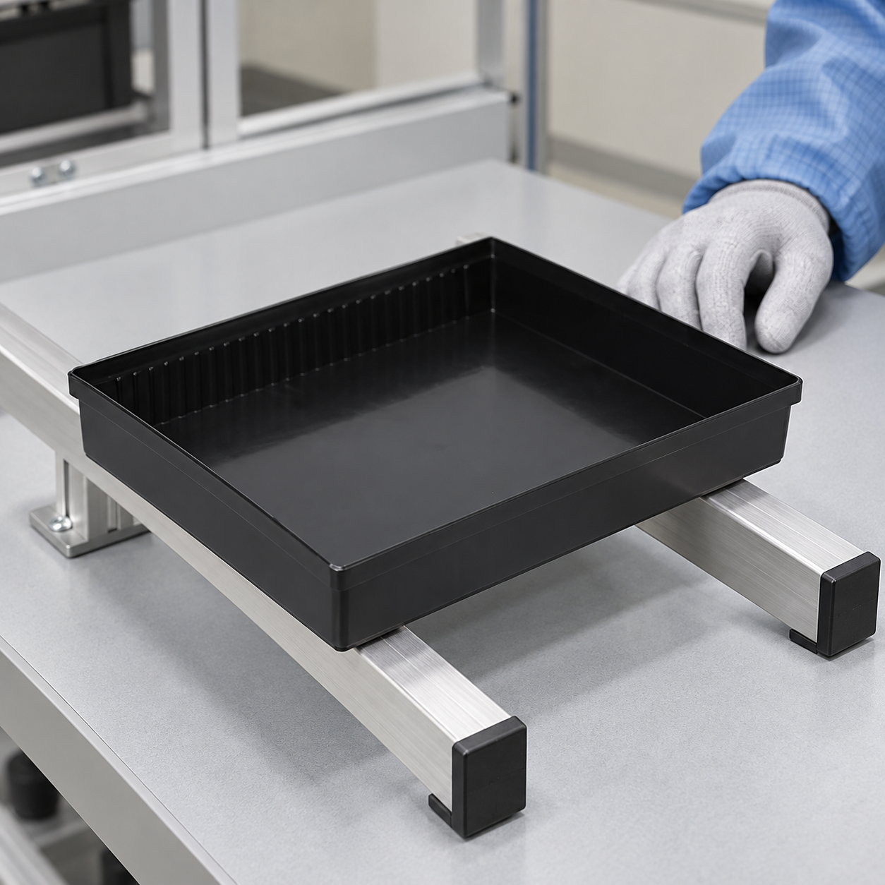
A flat worktable contacts much more of the base than two narrow rails. The same load can therefore produce very different deflection depending on where the support acts. Document the exact rail spacing, contact width, surface and orientation in the actual cart, rack, conveyor or automated handler. Include corners, handles or side features only if the approved tray design actually has them. If operators lift a loaded tray by its short sides, that handling position deserves its own evaluation; it cannot be inferred from a static bench test.
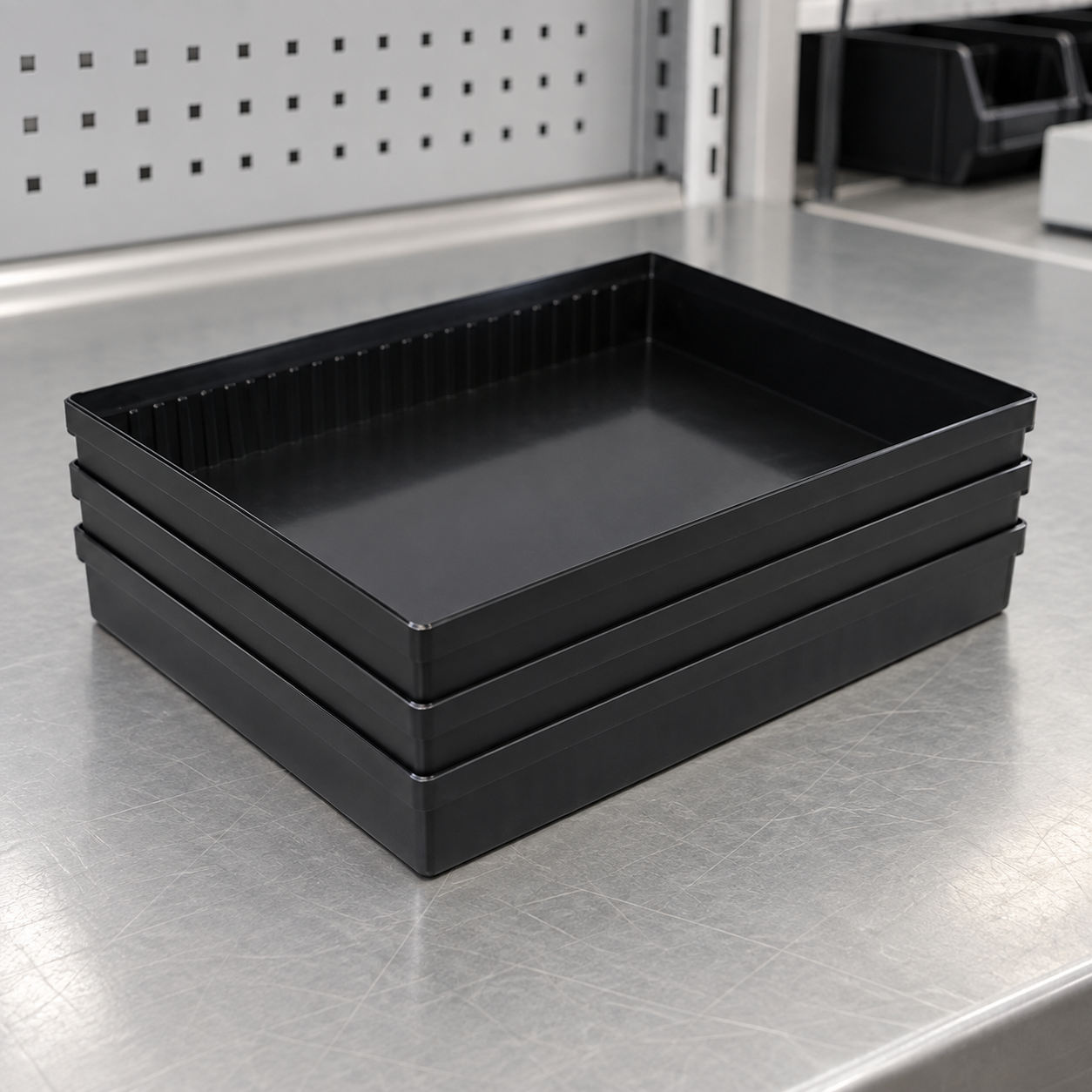
For a stacked configuration, clarify how the upper tray bears on the lower tray: on designed shoulders, rim, sidewalls or another interface. Check whether the load path bypasses the protected products. A tray that nests when empty may contact components or rock when it carries a tall assembly, a divider or a liner. Use the maximum authorized stack count and the intended cover, straps and outer packaging, not a two-tray demonstration that never represents production.
Distributed and Concentrated Loads Are Different
Small components spread across the base and one heavy item in the center do not impose the same local demand. A narrow foot, sharp corner or board edge can indent or crack plastic even if the total mass is below a distributed-load figure. Describe the contact footprint, position and restraint of each item. Where a divider or liner spreads the load, validate it as part of the assembly and confirm it does not shed particles, change ESD behavior or compress into the protected product.
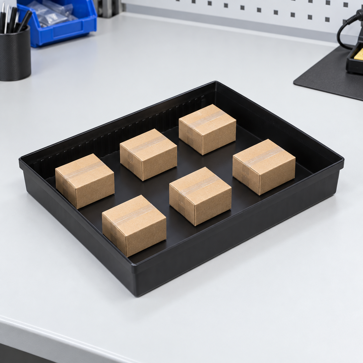
Use production-representative dummy packages for development trials when real assemblies are costly. Their mass, footprint and center of gravity must represent the worst permitted contents. Mark them clearly as test articles; a visually similar box with the wrong mass distribution is not an equivalent load. Do not place unprotected ESD-sensitive devices into a trial to make a photograph. The EOS/ESD Association’s control guidance explains why the electrical properties of handling containers must be assessed separately from mechanical fit.
A Practical Qualification Matrix
The following matrix turns “load capacity” into testable use cases. It intentionally provides no universal kilograms or millimeters: those limits must be agreed against the controlled device and equipment drawings, supplier data and trials. Record both the loaded condition and the result after unloading.
| Use case | Set up the test | Record and accept against the project specification |
|---|---|---|
| Flat, distributed load | Place identified dummy packages over the intended footprint on the approved bench support. | Payload mass, locations, initial and loaded deflection, visible damage and post-unload flatness. |
| Rail-supported load | Use the actual rail span, contact width and tray orientation. | Deflection at critical locations, rail retention, conveyor or rack clearance and recovery. |
| Concentrated item | Place the worst permitted footprint and center of gravity at the specified location. | Local indentation, cracking, rotation, contact with other items and permanent set. |
| Loaded stack | Build the authorized quantity using real covers, dividers and restraints. | Nesting alignment, cumulative height, product clearance, bottom-tray deformation and stability. |
| Normal movement | Repeat the specified lift, cart, conveyor and transfer sequence. | Item movement, tray retention, grip safety, shifting load and damage after repeated cycles. |
Use a controlled drawing to identify measurement datums and critical limits before testing. Do not decide after a trial that a bent tray is acceptable because the components happened to survive once. Conversely, a small elastic deflection may be acceptable if the project explicitly permits it and the tray recovers and functions; that judgement must be documented by the responsible engineers.
How to Run a Repeatable Load Trial
- Identify the samples. Record tray model, drawing revision, resin or construction, production lot, mold cavity when relevant, age and any prior reuse. Include the approved production process, not just a hand-made prototype.
- Condition them. Record temperature, humidity, storage history and exposure that matters to the intended route. Repeat after permitted cleaning or heat cycles when those can change the tray.
- Measure the unloaded baseline. Photograph and gauge flatness, sidewall integrity, rim alignment, stack fit and the equipment interface at named points.
- Load by an agreed sequence. Record mass, footprint, position, dwell time, support geometry and sequence. Stop safely when a stated abort condition appears; never test with valuable devices at risk.
- Observe the loaded condition. Measure deflection without pressing the tray flat. Check for wall spread, stress whitening, cracks, a lifted corner and unintended contact with components.
- Unload and recheck. Measure permanent set after the defined recovery interval and verify nesting, cover fit, label readability and equipment passage.
- Repeat across variation. Inspect samples from relevant production lots and cavities; use a risk-based sample count agreed with quality rather than presenting one favorable result as a rated capacity.
Keep the raw readings, instrument identification, photographs, acceptance limits and failure disposition. The supplier’s approved test method can provide a starting point, but the buyer must confirm its support and load conditions match the actual application. A certificate for the resin alone does not prove finished-tray capacity because wall thickness, corners, processing and geometry influence behavior.
Account for Transport, Reuse and Stacking
A static bench test does not simulate acceleration, vibration, drops or shifting contents during shipment. Qualify the complete package for its route where shipment is in scope. The International Safe Transit Association’s procedure overview provides a framework for selecting package-distribution tests; the correct procedure must be chosen for the finished pack, not treated as a tray material rating. In an internal factory route, reproduce the actual cart stops, transfers and operator lift points instead of assuming a parcel-shipment test covers them.
Repeated use may introduce cracks, worn nesting features, contamination and dimensional drift. Define a visual inspection at each return and periodic functional checks according to risk. A damaged tray should be segregated, and its previous use assessed if the failure could have exposed components to contact or impact. Do not set a universal reuse count from appearance alone; retirement depends on measurable criteria and the route’s history.
Keep Mechanical and ESD Approval Separate
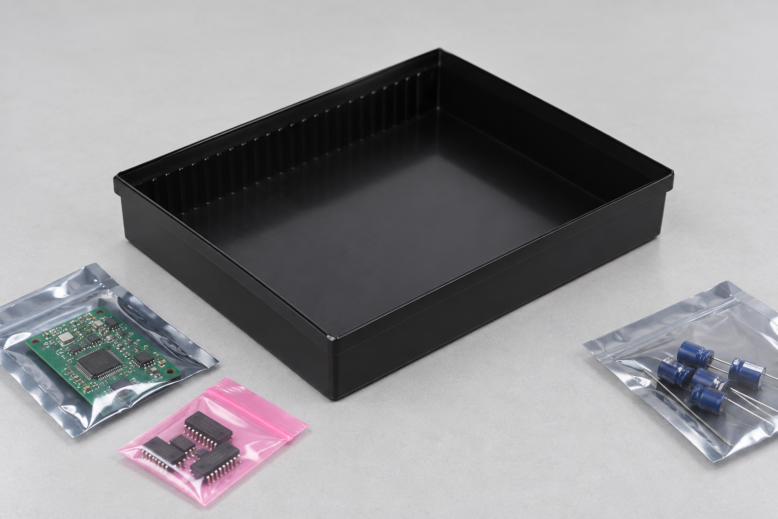
“ESD-safe” is not a mechanical load rating, and a mechanically strong tray is not automatically an appropriate ESD package. The EOS/ESD Association’s ANSI/ESD S541 packaging standard page describes packaging properties for ESD-sensitive items through production, transport and storage. Evaluate the relevant finished-tray surfaces, materials, inserts and route under the facility’s ESD control plan. The NASA electrostatic-discharge control standard is an additional authoritative control reference, not evidence that any SWESD tray meets a specific program.
Some fillers, coatings, cleaning processes, labels and dividers may change electrical performance while also altering stiffness or contact behavior. Require separate evidence for both functions after any material or tooling change. Inside and outside an electrostatic protected area can require different packaging protection; confirm the exact path before deciding that a tray alone is sufficient. Never infer conductive behavior from black color or infer shielding from a tray’s shape.
RFQ Checklist for Buyers
- Provide the protected item’s drawing, maximum and minimum envelope, mass, center of gravity and permitted contact surfaces.
- State tray quantity, intended loading pattern, allowable local contact pressure and movement constraints.
- Attach cart, shelf, conveyor and handling interface drawings with real support spacing and lift points.
- Specify stack count, cover, divider, liner, restraints, outer package and transport route.
- Define acceptance for loaded deflection, residual set, cracks, stack height, equipment fit and product clearance.
- Request tray material and lot identity, first-article records, sample size and change-notification rules.
- Ask separately for ESD material and finished-assembly evidence required by your control program.
- Agree what incoming inspection will measure and how damaged or untraceable trays will be contained.
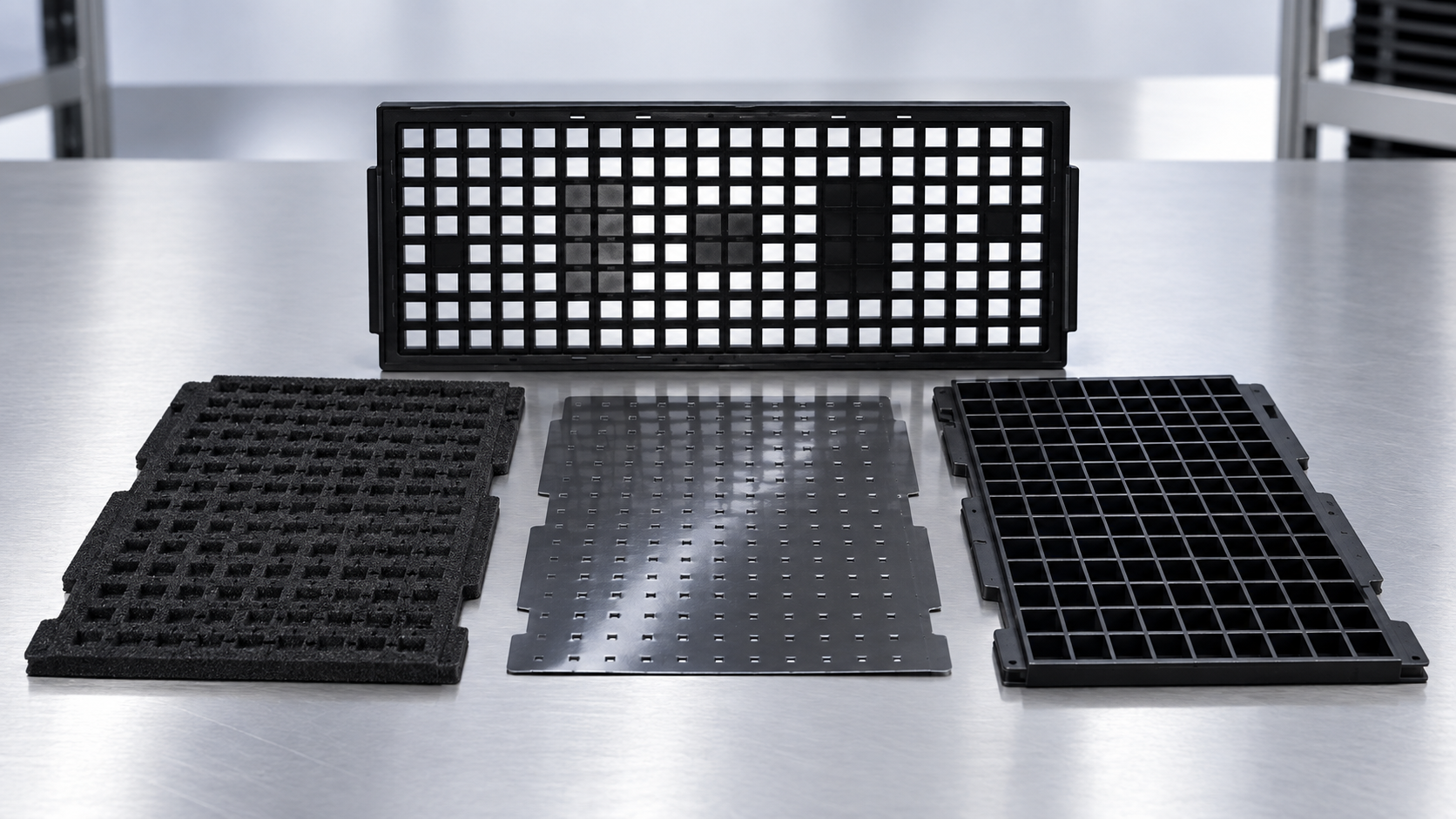
SWESD’s ESD tray product page shows relevant tray families; a buyer still needs model-specific approval evidence before assigning a load rating. For the broader packaging decision, see the anti-static SMT component tray guide. 。 line-side staging guide addresses workflow and dividers, while the ESD tray material selection guide addresses electrical and material choices. These related decisions should inform, not replace, a mechanical capacity trial.
Educational Video: The Separate ESD-Control Requirement
The EOS/ESD Association’s university lecture introduces electrostatic-discharge control. It helps explain why a tray’s mechanical qualification must be paired with electrical packaging requirements, but it does not test tray load capacity or certify a product.

よくある質問
Is there a universal load capacity for all ESD trays?
No. The rating depends on the exact design, material, support span, load position, conditioning and acceptance criteria. Request model- and use-specific evidence.
Can I use a flat-bench capacity for a trolley with two rails?
Not without a representative rail-supported trial. The changed support arrangement can alter bending and retention.
Does a distributed-load rating cover a heavy item in one corner?
No. Concentrated and eccentric loads require their own footprint and position check, including local deformation and item movement.
Does a strong tray automatically protect ESD-sensitive parts?
No. Mechanical support and electrostatic packaging performance are separate requirements; evaluate both under the actual handling route.
What should receiving inspect after qualification?
Check part and revision identity, cracks, rim and base distortion, nesting and equipment fit, and any lot-specific evidence required by the approved control plan.
Technical boundary: This article describes how to specify and validate capacity; it does not claim a measured SWESD load limit or endorse a universal test number. Final limits belong in the controlled drawing and qualification record for the specific tray and route.
コメントを送信