- Turbo
- Blog
ESD magazine rack grounding must be evaluated as part of the site’s complete ESD protected area (EPA), not by assuming that a metal frame automatically makes every slot safe. Determine which rack parts are conductive or dissipative, where sensitive PCB edges contact the rack, and how the rack is used on a bench, cart or automated interface. Then verify the intended bonding or equipotential path by the approved ESD control plan. A portable rack may lose a path when lifted off a grounded surface, and an insulating panel will not become grounded merely because it is bolted to metal. This guide gives buyers and engineers a practical qualification checklist without inventing a universal connection or resistance limit.
Identify the surfaces and contact path
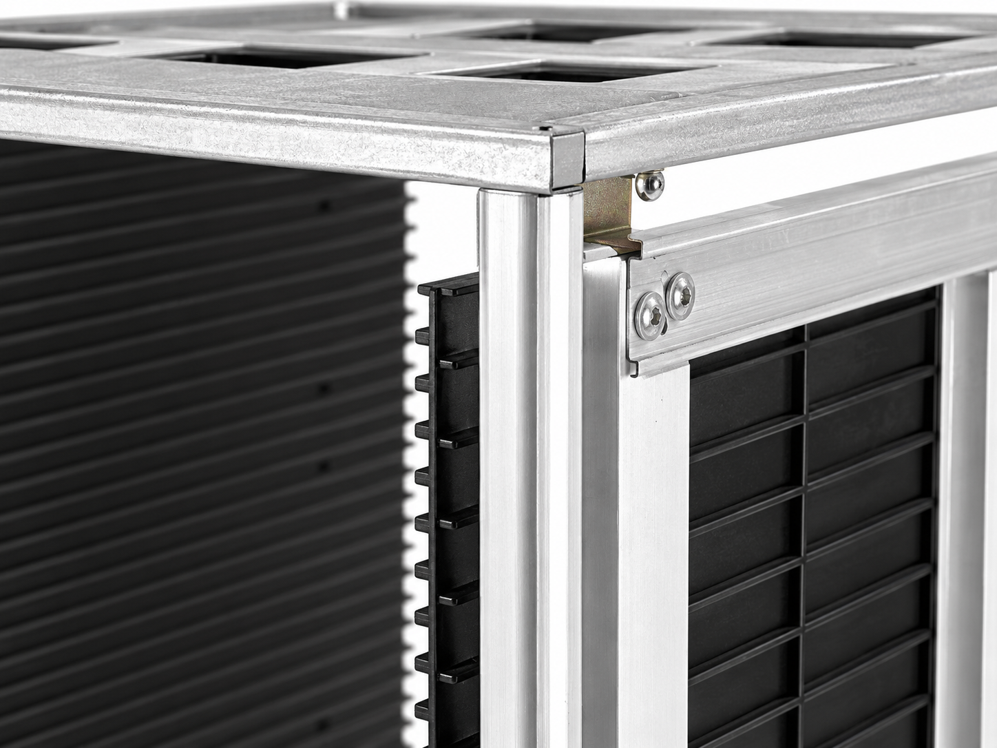
Look at the actual rack: frame, slot panels, base, fasteners, handles, adjustment rails and any wheels or feet. Mark where a PCB touches during insertion, storage and removal. A metal frame is only one part of the path. The board may contact a polymer groove, which may or may not be designed to dissipate charge. A painted or anodized joint can interrupt a path that looks continuous. Conversely, a hard metal contact at an exposed PCB feature may create a different risk than the design intended.
Itu EOS/ESD Association’s ESD control principles describe equipotential bonding of conductors and the role of controlled materials in an EPA. That principle should guide the rack evaluation, but it does not identify a specific terminal on a particular SWESD product. Obtain the product’s controlled drawing and qualification evidence before deciding where, whether or how a connection is made.
Define the use case before choosing a grounding method
Will the rack remain on one approved work surface, sit on a trolley, move between workstations, or enter equipment? Is it loaded only inside the EPA? Does it cross an uncontrolled area? The answer changes what the site must verify. A rack connected through a work surface may lose that path during transport. A trolley may require its own qualified flooring and grounding arrangement. A rack outside an EPA may need appropriate protective packaging; a ground lead does not create discharge shielding.
Map the whole handling sequence from empty-rack setup to board removal. Record when operators touch the frame and when boards are exposed. The EOS/ESD Association’s materials and grounding guidance describes common-point ground and equipment grounding conductors as part of a broader workstation system. The site ESD coordinator should apply those principles to the exact rack and route, rather than copying a wiring diagram from a different factory.
Do not confuse conductive appearance with an approved path
Silver-colored rails are not proof that every joint is electrically connected. Black plastic is not proof of a particular resistance range. Coatings, oxide, fastener torque, contamination, replacement parts and worn contact areas can change the result. Inspect the assembled rack, not a bare material sample. If the rack has adjustable panels, test it in the positions used for the smallest and largest boards. A continuity result at one setting may not cover another setting.
Neither should a buyer assume that lower resistance is always better. The site’s approved standard, device sensitivity, material design and contact location determine the suitable control. The EOS/ESD Association’s explanation of discharge paths distinguishes bonding, static-dissipative surfaces and isolated conductors. Request the actual test method and conditions behind a supplier claim. Avoid accepting “conductive” or “ESD safe” without an application and measurement record.
Write a test plan before attaching a lead
Identify the applicable site procedure, instrument, verification interval and acceptance limits. Record rack model and revision, panel setting, test locations, environmental conditioning and who performs the test. The ESD TR53 compliance-verification overview shows that ESD protective equipment and materials are checked through defined methods; it is not permission to invent a new meter setup in an article. Use the actual standard and procedure held by the site.
Check the intended path in every normal operating state: stationary, loaded, adjusted, moved and returned to its position. Confirm that cables, clamps or contact points will not obstruct loading, snag on boards or be disconnected during routine handling. Do not drill an improvised hole or attach a wire to an unknown rack surface. Changes to the product can invalidate its mechanical and electrical qualification and may introduce a sharp edge near a PCB.
Use a qualification table for the complete rack
| Control question | Evidence to request or test | Reason it matters |
|---|---|---|
| Contact surfaces | Material list and contact-zone drawing | Board touches grooves, not only the frame |
| Assembled path | Site-approved electrical measurement at defined points | Joints and coatings can interrupt continuity |
| Adjustment positions | Results at approved width settings | Moving panels may alter a connection |
| Portable operation | Route map and state-specific verification | Lifted racks may lose surface contact |
| Maintenance state | Post-cleaning and post-repair recheck | Residue and replacement parts can change behavior |
| Outside-EPA movement | Approved packaging configuration | Grounding alone does not supply shielding |
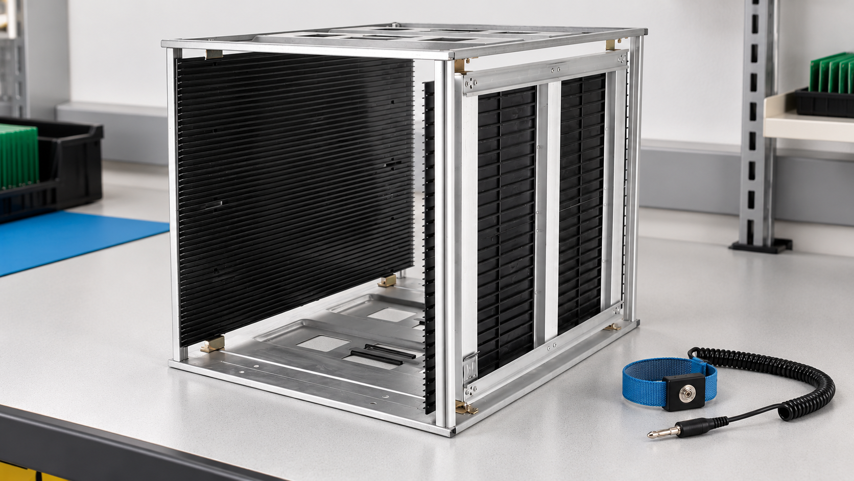
Keep the site’s actual numerical limits in its controlled plan, not in a generic web table. The illustrated metal-base ESD magazine rack is a physical example. Its specific material, conductive path and approved test conditions must be confirmed for the purchased revision. A product photo is not test evidence.
Evaluate the rack on each supporting surface
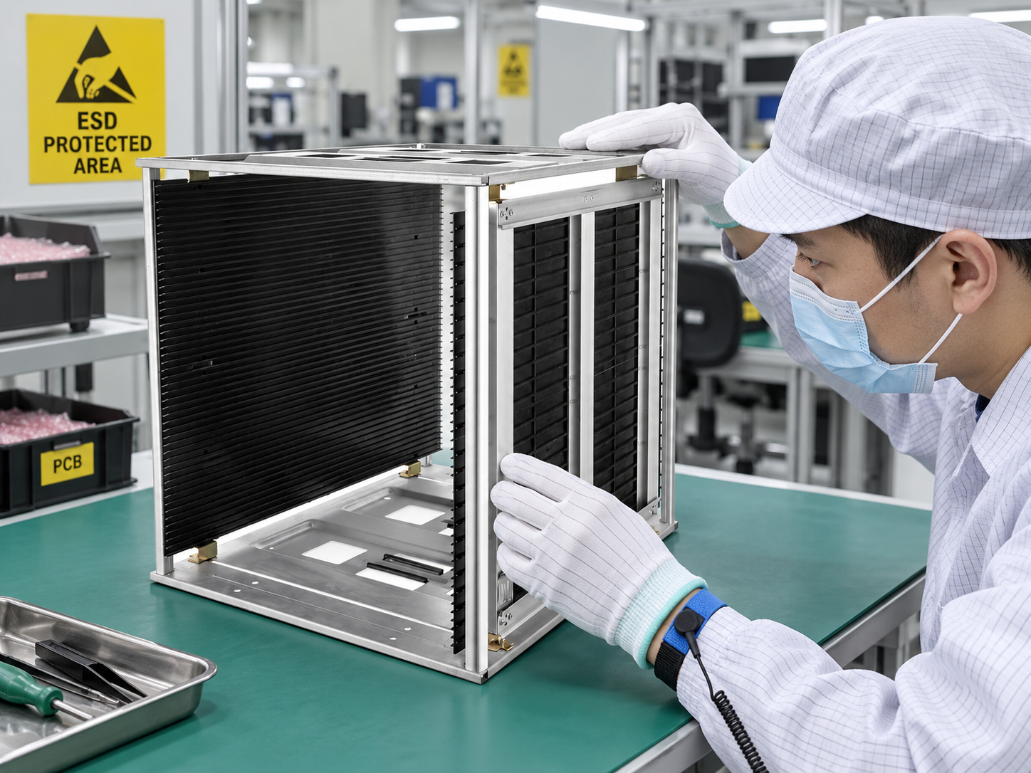
On a bench, confirm that the work surface and rack position are included in the EPA setup. On a cart, consider floor, wheel and cart-frame control under the site’s approved arrangement. In automated equipment, confirm the transfer interface and machine grounding design with the equipment owner. Do not assume a rack resting on metal has a reliable path: paint, rubber feet, vibration or intermittent contact may change it. If the rack is lifted, define how boards stay protected during that period.
Observe operators as they load and unload. Personal grounding, work-surface control and rack material are separate controls that must work together. If a board is removed and placed on an uncontrolled table, qualifying the magazine rack alone has not protected the workflow. The ESD rack for SMT overview discusses its line role; this article focuses on the electrical-control decision.
Check for isolated conductors and accidental contacts
A small metal handle, screw head or clamp can be isolated from the intended ground path. If it can approach or touch a sensitive assembly, include it in the risk review. Do not simply connect every visible metal part with a random wire: the design owner should decide whether bonding, separation, insulation, a dissipative interface or another control is appropriate. Avoid exposed fastener ends near board traces or components.
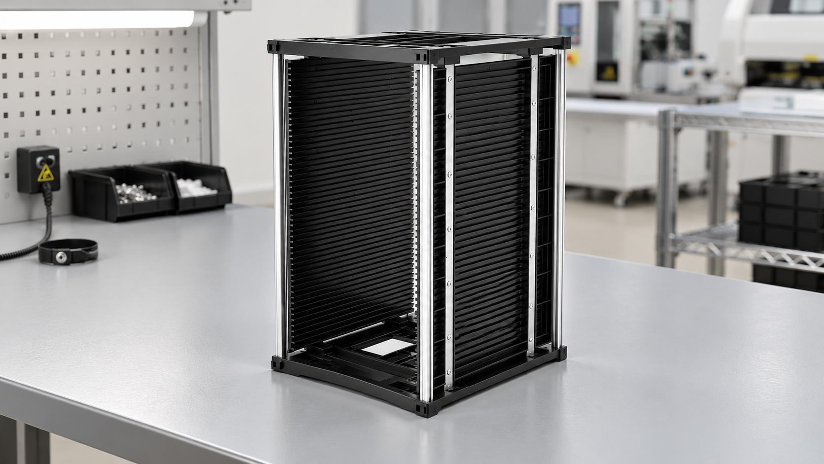
In a rack with replaceable panels, verify the approved panel revision and mounting method. A replacement that looks identical could have different material or surface properties. The metal-base versus plastic-base comparison addresses mechanical and material choices; it does not establish a grounding verdict for every assembly. Use actual qualification records for the selected model.
Control cleaning, repair and recurring verification
Cleaning residue, abrasion and corrosion can alter contact surfaces. Inspect and verify racks after significant cleaning or repair according to the site’s plan. Record rack ID, instrument, method, location, result and disposition. If a result fails, segregate the rack and protect any affected boards before investigating. A repeated measurement without addressing a loose joint or wrong setup is not a corrective action.
Assign ownership: procurement obtains evidence, engineering approves the configuration, the ESD coordinator owns electrical limits, maintenance controls repairs and operators follow the handling procedure. The PCB magazine rack cleaning guide
Specify the RFQ and acceptance trial
Send the intended EPA locations and transport route, PCB contact zones, rack size and adjustment range, required materials and ESD plan references, expected load, cleaning process, supporting bench or cart and verification method. Ask the supplier for a controlled drawing, material and assembly test evidence, approved grounding arrangement if any, replacement-part controls and a sample. State that the trial will check both electrical performance and safe board loading in the actual workflow.
Do not allow an unverified grounding claim to substitute for mechanical fit. The slot-width guide
Further learning: ESD principles
The EOS/ESD Association’s introductory lecture explains charge, discharge and the purpose of controlled handling. It does not replace the site’s rack-specific grounding plan.

Pertanyaan yang sering diajukan
Does a metal magazine-rack frame automatically need a wire?
No. The approved EPA design and measured path determine whether and how the assembled rack is bonded.
Can a black slot panel be assumed conductive?
No. Confirm its material and electrical performance for the exact product revision and test method.
Will a grounded rack protect boards outside an EPA?
Not by itself. Movement outside an EPA may require qualified protective packaging, including shielding where applicable.
When should grounding be rechecked?
Use the site’s compliance-verification interval and recheck after material, adjustment, repair or supporting-surface changes.
What should be recorded after a failed test?
Record rack ID, configuration, test point, method, instrument, result, affected product, containment and corrective action.

Tinggalkan Balasan